Page 78 of 102 Page 79 of 102Doc: DRX Installation
Version: 7.1 January 2021
Doc: DRX Installation
Version: 7.1 January 2021
wassp.com wassp.com
DRX INSTALLATION MANUAL DRX INSTALLATION MANUAL
APPENDIX A.3 TRANSDUCER TX
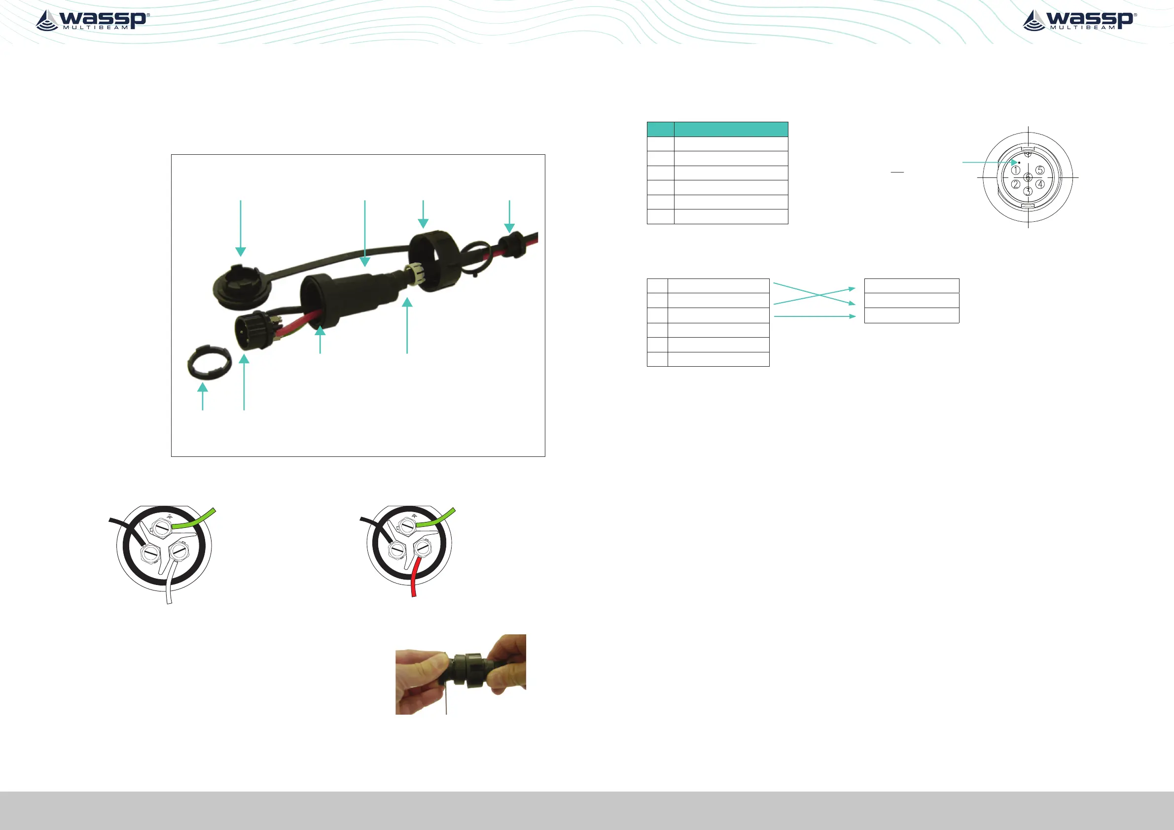
Transmitter Cable Socket Assembly
If the transmitter cable socket needs to be disassembled, use the locking ring tightening
tool (supplied with the DRX) to loosen the locking ring. To assemble the 3-pin sealed
plug:
Push the following
parts over the
transmitter wires:
• Gland Nut
• Gland Cage
• Gland
• Main Body
Locking Ring
Tightening Tool
Locking Cap Gland NutGland
Locking
Ring
Socket
Gland CageMain Body
1. Attach the RED or WHITE wire to L, the BLACK wire to N, and the GREEN wire to E
on the socket and tighten all three screws.
Later Cable Colour Code
E
L
N
RED
GREEN
BLACK
Early Cable Colour Code
2. Push the socket into the main body, making
sure that the flat on the socket locates into the
flat on the main body.
3. Using the tightening tool, screw the locking ring
into the front of the socket until tight.
4. Push the gland, gland cage, and gland nut into
the main body as far as it will go and tighten the
nut securely.
Tightening tool
APPENDIX A.4 RS232
Connector RS-232
PIN Function
Marker identifies pin 1.
View: Looking into the socket on the
DRX. Wiring view of cable side on plug.
1 RS-232_Tx
2 RS-232_Rx
3 RS-232_GND
4
5 9-32V+
6 9-32V-
Example Connection:
1 RS-232_Tx RS-232_Tx
2 RS-232_Rx RS-232_Rx
3 RS-232_GND RS-232_GND
4
5 9-32V+
6 9-32V-
» Isolation; Fully electrically isolated.
» Cable; Multi core or multi core screened with tinned copper conductors.
 Loading...