Page 80 of 102 Page 81 of 102Doc: DRX Installation
Version: 7.1 January 2021
Doc: DRX Installation
Version: 7.1 January 2021
wassp.com wassp.com
DRX INSTALLATION MANUAL DRX INSTALLATION MANUAL
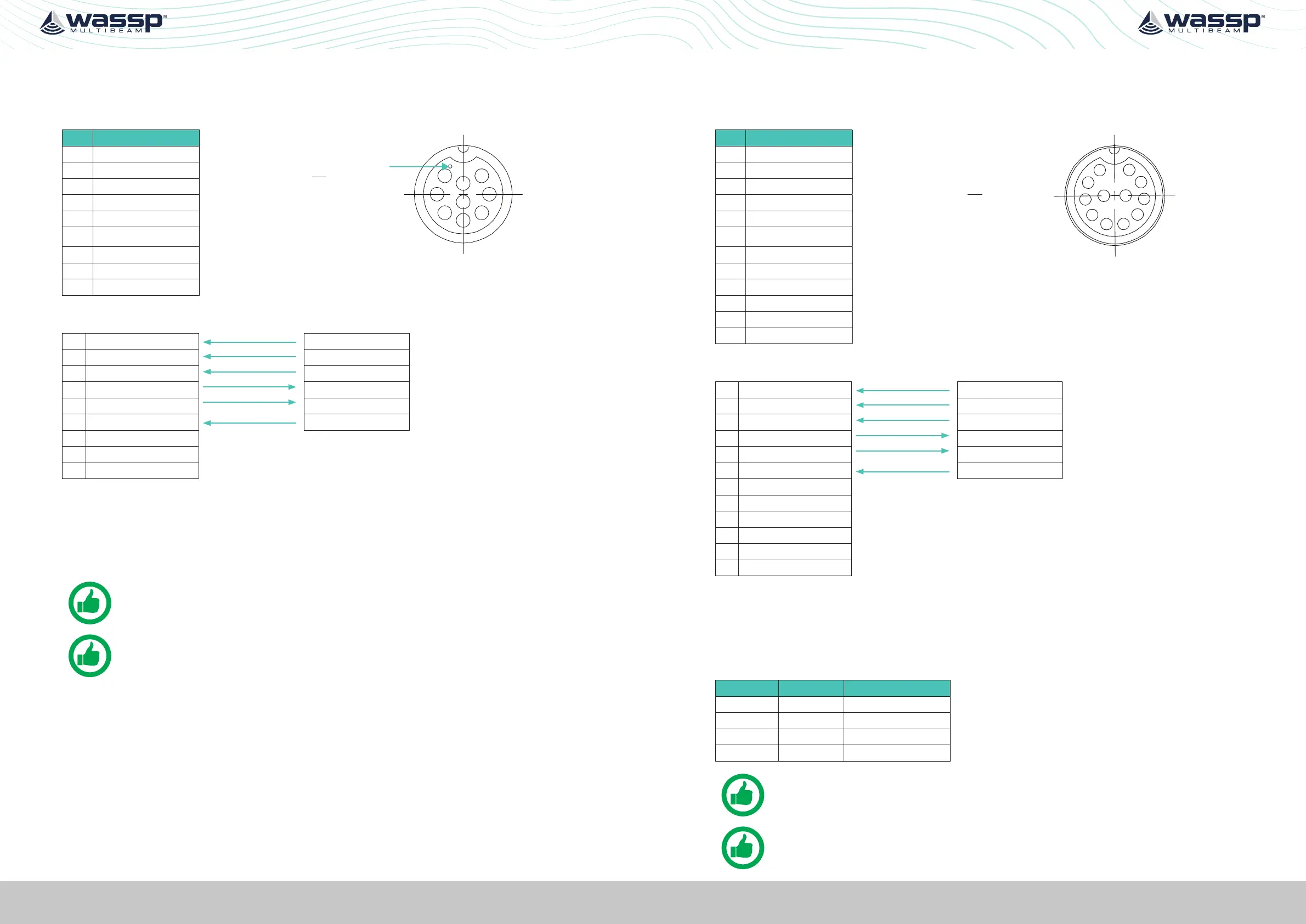
APPENDIX A.5 RS422A
Connector RS422-A
PIN Function
1
2
3
4
5
6
7
8
9
Marker identifies pin 1.
View: Looking into the socket on the
DRX. Wiring view of cable side on plug.
1 PPS (AUX)
2 RxD B
3 RxD A
4 TxD B
5 TxD A
6 GND
7
8 9-32V+
9 9-32V-
Example Connection:
1 PPS (AUX) PPS OUT
2 RxD B
TxD +
3 RxD A TxD -
4 TxD B RxD +
5 TxD A RxD -
6 GND
PPS OUT GND
7
8 9-32V+
9 9-32V-
» Isolation; Fully electrically isolated.
» Cable; Multi core screened with tinned copper conductors.
» Shield; Should be connected at far end.
NOTE: Depending on sensor compliance, this may be used as
direct NMEA 0183 input.
NOTE: Depending on equipment, Rx / Tx polarity may be labelled B and A
or + and -. This polarity must be maintained as per the example.
APPENDIX A.6 RS422B
Connector RS422-B
PIN Function
10
9
1
2
12
11
83
7
6
5
4
View: Looking into the socket on the
DRX. Wiring view of cable side on plug.
1 PPS (AUX)
2 RxD B
3 RxD A
4 TxD B
5 TxD A
6 GND
7 RESERVED
8 RESERVED
9 RESERVED
10 RESERVED
11 9-32V-
12 9-32V+
Example Connection:
1 PPS (AUX) PPS OUT
2 RxD B
TxD +
3 RxD A TxD -
4 TxD B RxD+
5 TxD A RxD -
6 GND
PPS OUT GND
7 RESERVED
8 RESERVED
9 RESERVED
10 RESERVED
11 9-32V-
12 9-32V+
» Isolation; Fully electrically isolated.
» Cable; Multi core screened with tinned copper conductors.
» Shield; Should be connected at far end.
RS422B Internal DRX wiring of reserved pins is as follows:
RS422B Pin RS422A pin Function
7 2 RS422A RxB
8 3 RS422A RxA
9 1 RS422A PPS+
10 6 RS422A PPS-
NOTE: Depending on sensor compliance, this may be used as
direct NMEA 0183 input.
NOTE: Depending on equipment, Rx / Tx polarity may be labelled B and A
or + and -. This polarity must be maintained as per the example.
 Loading...