Page 82 of 102 Page 83 of 102Doc: DRX Installation
Version: 7.1 January 2021
Doc: DRX Installation
Version: 7.1 January 2021
wassp.com wassp.com
DRX INSTALLATION MANUAL DRX INSTALLATION MANUAL
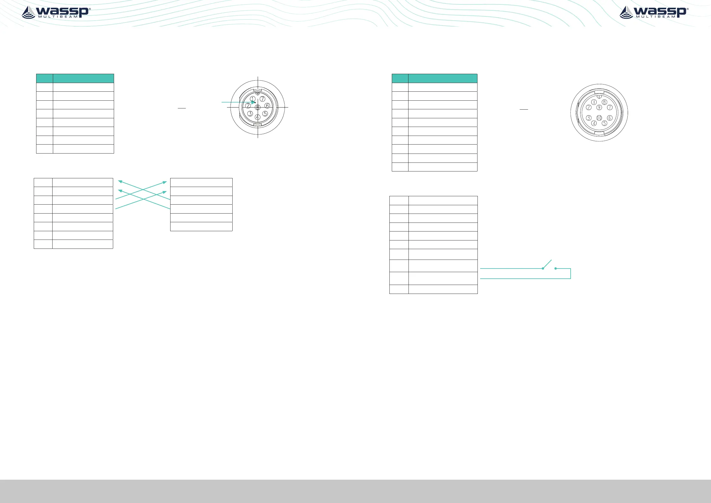
APPENDIX A.7 NMEA 0183
Connector 0183
PIN Function
Marker identifies pin 1.
View: Looking into the socket on the
DRX. Wiring view of cable side on plug.
1 NMEA0183 IN B
2 NMEA0183 IN A
3 NMEA0183 OUT B
4 NMEA0183 OUT A
5 GND (Shield)
6 PPS_in
7 PPS_in GND
8
Example Connection:
1 NMEA0183 IN B NMEA0183 IN B
2 NMEA0183 IN A NMEA0183 IN A
3 NMEA0183 OUT B NMEA0183 OUT B
4 NMEA0183 OUT A NMEA0183 OUT A
5 GND (Shield) PPS OUT +
6 PPS_in PPS OUT GND
7 PPS_in GND
8
» Isolation; Input electrically isolated. Output isolation, if required, should be at receive
end.
» Cable; Multi core screened with tinned copper conductors.
APPENDIX A.8 REMOTE POWER
Connector AUX
PIN Function
View: Looking into the socket on the
DRX. Wiring view of cable side on plug.
1 KP1_in
2 KP1_in_GND
3 KP2_in
4 KP2_in_GND
5 KP1_OUT
6 +5.5V Isolated
7 GND(5.5V,KP1_OUT)
8 REMOTE_PWR_ON
9 REMOTE_PWR_ON_GND
10
Example Connection:
1 KP1_in
2 KP1_in_GND
3 KP2_in
4 KP2_in_GND
5 KP1_OUT
6 +5.5V Isolated
7 GND(5.5V,KP1_OUT)
8
REMOTE_PWR_ON
9
REMOTE_PWR_ON_GND
10
 Loading...