Page 34 of 102 Page 35 of 102Doc: DRX Installation
Version: 7.1 January 2021
Doc: DRX Installation
Version: 7.1 January 2021
wassp.com wassp.com
DRX INSTALLATION MANUAL DRX INSTALLATION MANUAL
5 SENSOR CONFIGURATION
The WASSP system requires position, heading, attitude, heave and time information
in order to be fully functional. The overall performance will be directly aected by the
quality of the sensors chosen and being configured as described below.
WASSP supplies sensor package kits for recommended install. See the WASSP Sensor Box
Installation Manual for detailed information.
For supported sensors and sentences, see “Appendix B - Supported Sensors and
Sentences” on page 87.
NOTE: Currently support sensors and sentences will depend on software
version and can be found at wassp.com
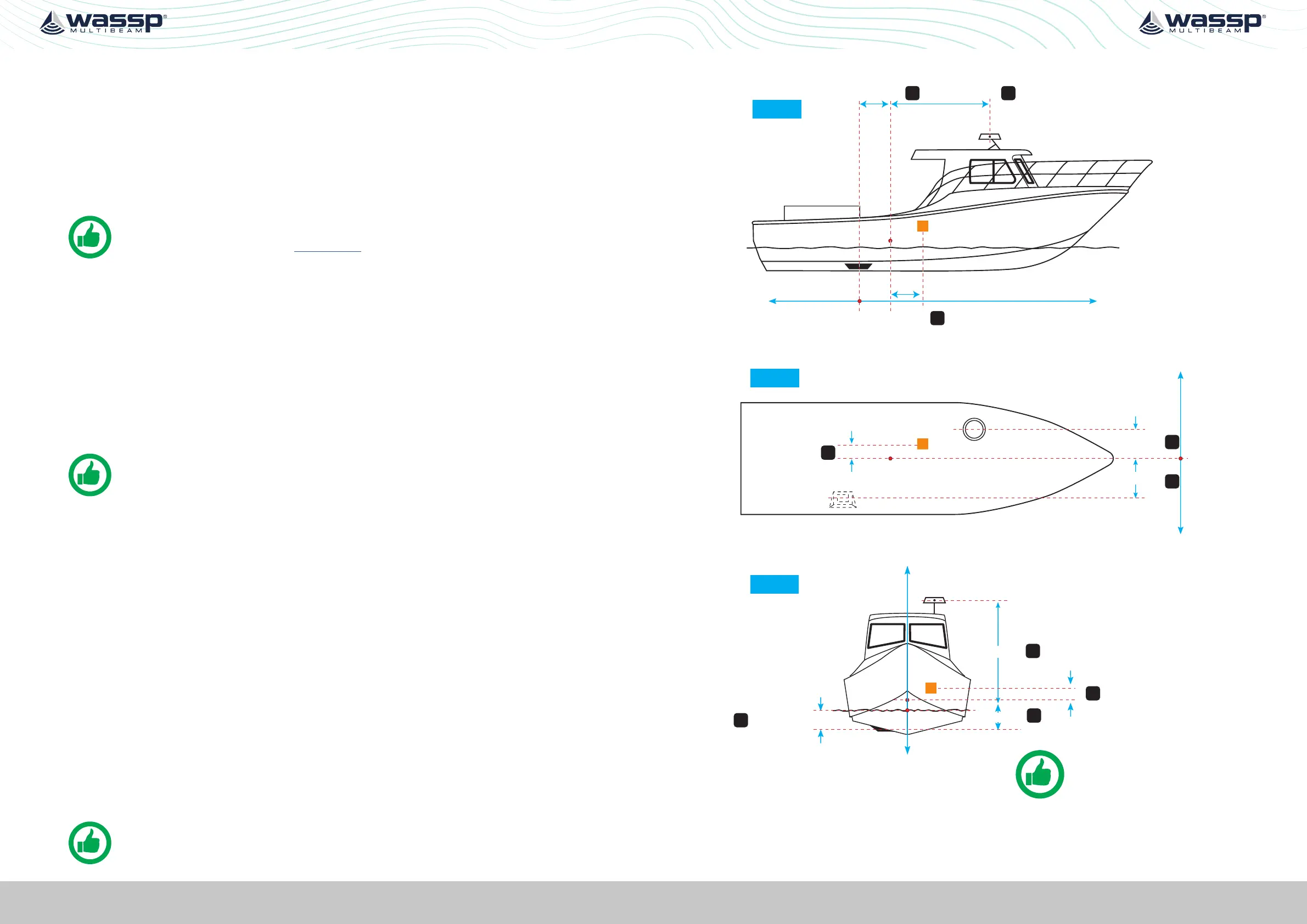
5.1. COMMISSIONING STEP 1: SHIP MEASUREMENTS
Take measurements from the GPS antenna, motion sensor and transducer to the vessel’s
reference point. See “Figure 17. Ship Measurements Diagram” on page 35.
These measurements must be as accurate as possible and should be measured to cm
level accuracy. The accuracy of these measurements have a direct impact on the WASSP
Multibeam performance. Position to measure from on the transducer, GPS antenna and
motion sensor is described in”Appendix D - Ship’s Measurement Points” on page 94.
Enter these values in the spaces below, and in the SENSOR INSTALLATION tab within the
SENSOR tab of the DRX SETUP WEBPAGES. See “Figure 20. DRX Setup, Sensor Tab” on
page 39.
NOTE: The Ship’s Reference Point needs to be a point on the vessel that
is easy to measure to and should be located with this in mind. The actual
position of the Reference Point is unimportant but should be clearly marked
and measurements between the sensors and the Reference Point made as
accurately as possible.
Transducer (XDCR) Depth (Draft) Displacement: m
🅰_______
GPS X Displacement from reference: m 🅱_______
GPS Y Displacement from reference: m _______
GPS Z Displacement from reference: m _______
Transducer (XDCR) X Displacement from reference: m _______
Transducer (XDCR) Y Displacement from reference: m _______
Transducer Z Displacement from reference: m _______
Motion Sensor X Displacement from reference: m _______
Motion Sensor Y Displacement from reference: m _______
Motion Sensor Z Displacement from reference: m _______
NOTE: Separate sensors can be used for GPS data, heading, roll, pitch and
heave as required. Make sure to note down all Sensor oset.
Sensor Installation
GPS
XDCR
R
GPS Z (-)
XDCR Z (+)
Transducer Draft
Z axis
Sky
Negative
Sea
Positive
R = Ship’s Reference Point
IMU Z (-)
R
XDCR
X axis
GPS X (+)
XDCR X (-)
GPS
Stern
Negative
Bow
Positive
Reference
Y axis
R
XDCR
GPS Y (-)
XDCR Y (+)
GPS
Port
Negative
Reference
Starboard
Positive
Looking from above
TIP: Transducer Draft is used
to adjust for true depth from
sea level.
A
B
G
D
E
H
F
C
IMU
IMU X (+)
IMU Y (-)
I
J
Figure 17. Ship Measurements Diagram
 Loading...