Page 84 of 102 Page 85 of 102Doc: DRX Installation
Version: 7.1 January 2021
Doc: DRX Installation
Version: 7.1 January 2021
wassp.com wassp.com
DRX INSTALLATION MANUAL DRX INSTALLATION MANUAL
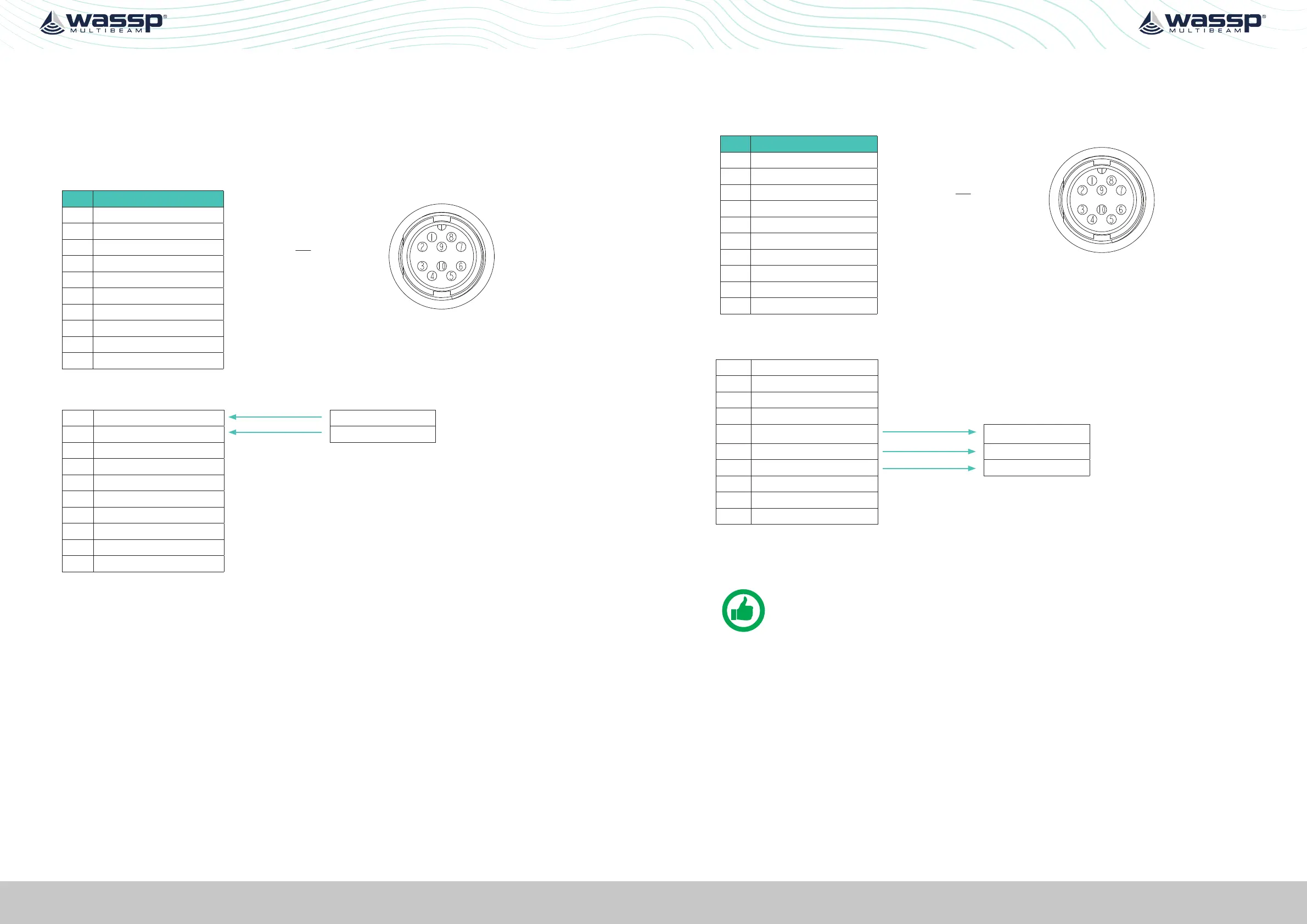
APPENDIX A.9 KP1/KP2 IN
Connector AUX
A Key Pulse (KP) can be connected to/from the sensor port of the DRX connection plate.
Input can detect a short circuit in addition to a voltage ranging from 0 - 15 V. See “KP (Key
Pulse) Settings” operating the WASSP system with a key pulse.
PIN Function
View: Looking into the socket on the
DRX. Wiring view of cable side on plug.
1 KP1_in
2 KP1_in_GND
3 KP2_in
4 KP2_in_GND
5 KP1_OUT
6 +5.5V Isolated
7 GND(5.5V,KP1_OUT)
8 REMOTE_PWR_ON
9 REMOTE_PWR_ON_GND
10
Example Connection:
1 KP1_in KP H
2 KP1_in_GND KP C
3 KP2_in
4 KP2_in_GND
5 KP1_OUT
6 +5.5V Isolated
7 GND(5.5V,KP1_OUT)
8 REMOTE_PWR_ON
9 REMOTE_PWR_ON_GND
10
» Isolation; Fully electrically isolated.
» Drive; Selectable as high, low or auto.
APPENDIX A.10 KP1 OUT
Connector AUX
PIN Function
View: Looking into the socket on the
DRX. Wiring view of cable side on plug.
1 KP1_in
2 KP1_in_GND
3 KP2_in
4 KP2_in_GND
5 KP1_OUT
6 +5.5V Isolated
7 GND(5.5V,KP1_OUT)
8 REMOTE_PWR_ON
9 REMOTE_PWR_ON_GND
10
Example Connection:
1 KP1_in
2 KP1_in_GND
3 KP2_in
4 KP2_in_GND
5 KP1_OUT
KP IN H
6 +5.5V Isolated +VIN
7 GND(5.5V,KP1_OUT)
KP IN C
8 REMOTE_PWR_ON
9 REMOTE_PWR_ON_GND
10
» Isolation; Fully electrically isolated.
NOTE: For DRX serial numbers below #360 please refer to WASSP DRX
Installation Manual Version 4.0, as output isolation, if required, should be at
receive end.
 Loading...