2-12 Setting Up the Detector
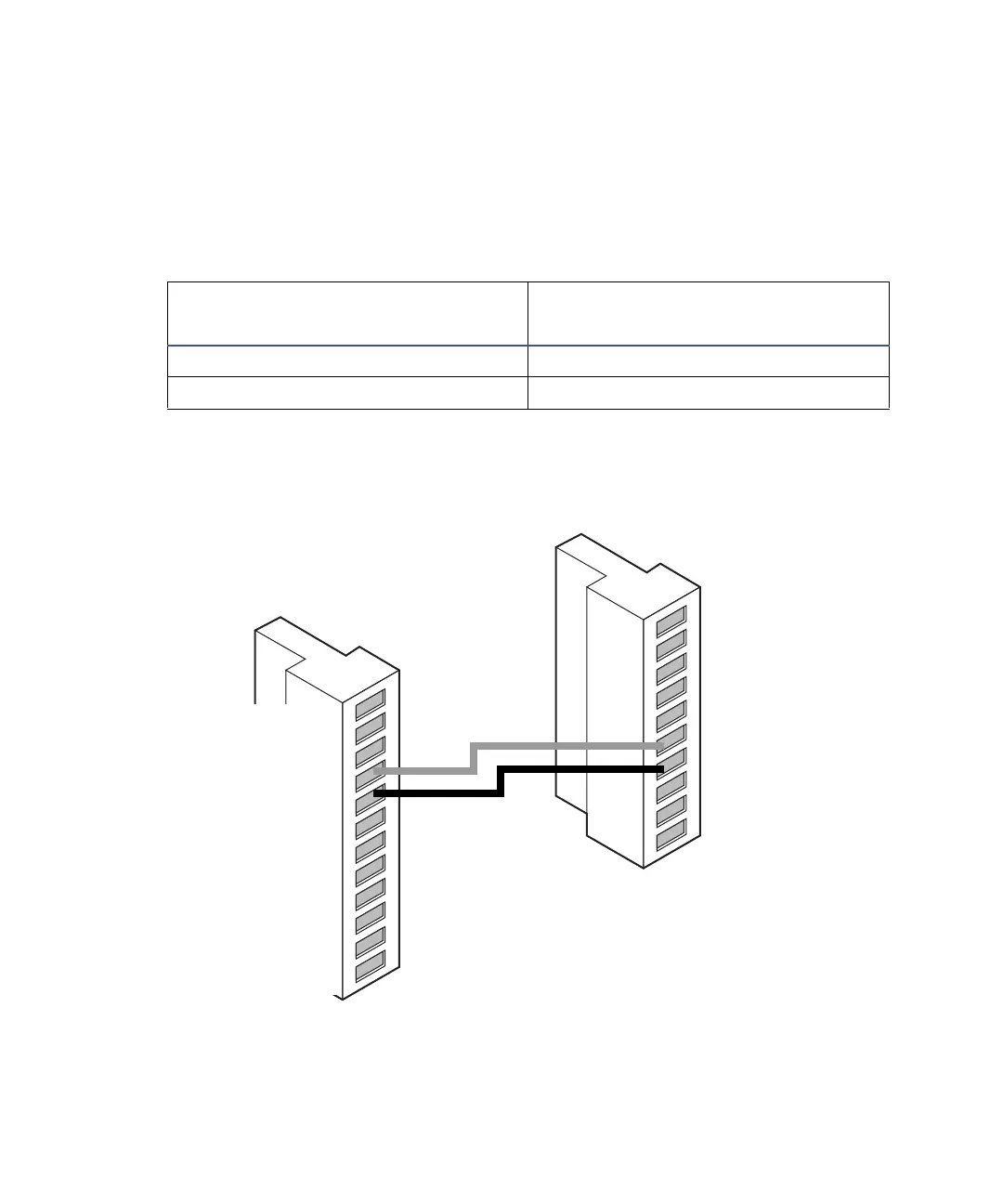
To generate stop flow, make the connections shown in the following table and
figure.
Requirement: To automatically stop the chromatographic flow to the system
in the event of an error condition or hardware failure, the stop flow signal
must be connected to the chromatographic pump.
Stop flow connections between the Alliance separations module and the
detector
Detector connections to an Alliance separations module
Alliance separations module
(connector B)
2998 PDA detector (connector B)
Pin 4 stop flow + (red) Pin 6 switch 1 + (red)
Pin 5 stop flow – (black) Pin 7 switch 1 – (black)
Red
Black
1
2
3
4
5
6
7
8
9
10
+
−
+
−
+
−
+
−
Analog 1
Analog 1
Ground
Analog 2
Analog 2
Switch 1
Switch 1
Ground
Switch 2
Switch 2
1
2
3
4
5
6
7
8
9
10
11
12
+
−
+
−
+
−
+
−
Inject Start
Inject Start
Ground
Stop Flow
Stop Flow
Hold Inject 1
Hold Inject 1
Hold Inject 2
Hold Inject 2
Ground
Chart Out
Chart Out
Waters Alliance connector B
2998 PDA detector connector B