Test Results
D
RESULt6 Freq.Off. Deviation of mobile transmit frequency from its rating
(receive frequency of Communication Test Set).
RESULt7 Power Average RF power of mobile(missing measurement va-
lue? See box "No PWR figure?" on page 10-24).
RESULt8 ∆
∆∆
∆P/Symbol Measure of continuous alteration of power, measured
for duration of slot and normalized to symbol. Ideal
figure = 0; positive value for increasing power and nega-
tive value for decreasing power.
RESULt9 Origin offs. Measure of erroneous DC offset of RMS vector. Ideal
figure = –
∞
; in IS-55 recommended minimum perfor-
mance: < –20 dB.
RESULtA RMS vec. err Average residual vector error, measured on 156 sym-
bols (one burst). Residual means after arithmetic
elimination of frequency offset, power alteration and
origin offset plus normalization of power. Residual error
includes both magnitude and phase error at maximum
effect points. Average residual error of mobile transmit
signal must not be greater than 12.5 %.
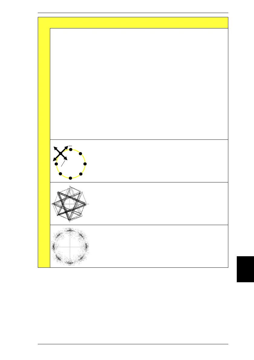
In (theoretical) ideal case constellation display shows
eight points arranged on 360° circle and 45° apart (RMS
vector on points of maximum effect). The greater the
phase and magnitude error of the RMS vector is, the
further the points are from these ideal positions.
Constellation display of well aligned modulator. Points
are closely grouped about eight ideal positions (high
modulation quality). The longer the measurement lasts
(for statistical presentation), the tighter the populations
of points become around the ideal positions.
Constellation display of poorly aligned modulator.
Points are far from ideal positions because of substan-
tial phase and magnitude fluctuations of RMS vector.
D
phase
D
magnitude
10
Modulation Quality IS-136 MS
10-35