Back Panel
Compatibility with Other Options
Bu
103
5/6
D-AMPS 236 044
Bu106
Bu105
Bu103
Bu104
Bu107 Bu108
3
IF UNIT 229 065
9
MONITOR CONTROL 236 032
10
HOST COMPUTER 250 033
POWER SUPPLY 204 031
St2
St1
7
SLAVE COMPUTER 250 0 34
4
Bu27
Bu29
MOD GEN ERATOR A 2 08 02 9
2
Bu90
Bu95
Bu91 Bu92
Bu93
Bu94
OPTION CARD 236 033
1
Bu15
Bu12
Bu13
AF DETECTOR 209 031
10 MHz REFERENCE 210 031
8
Bu99
Bu97
Bu98
S101
DATA MODUL 236 034
Bu20
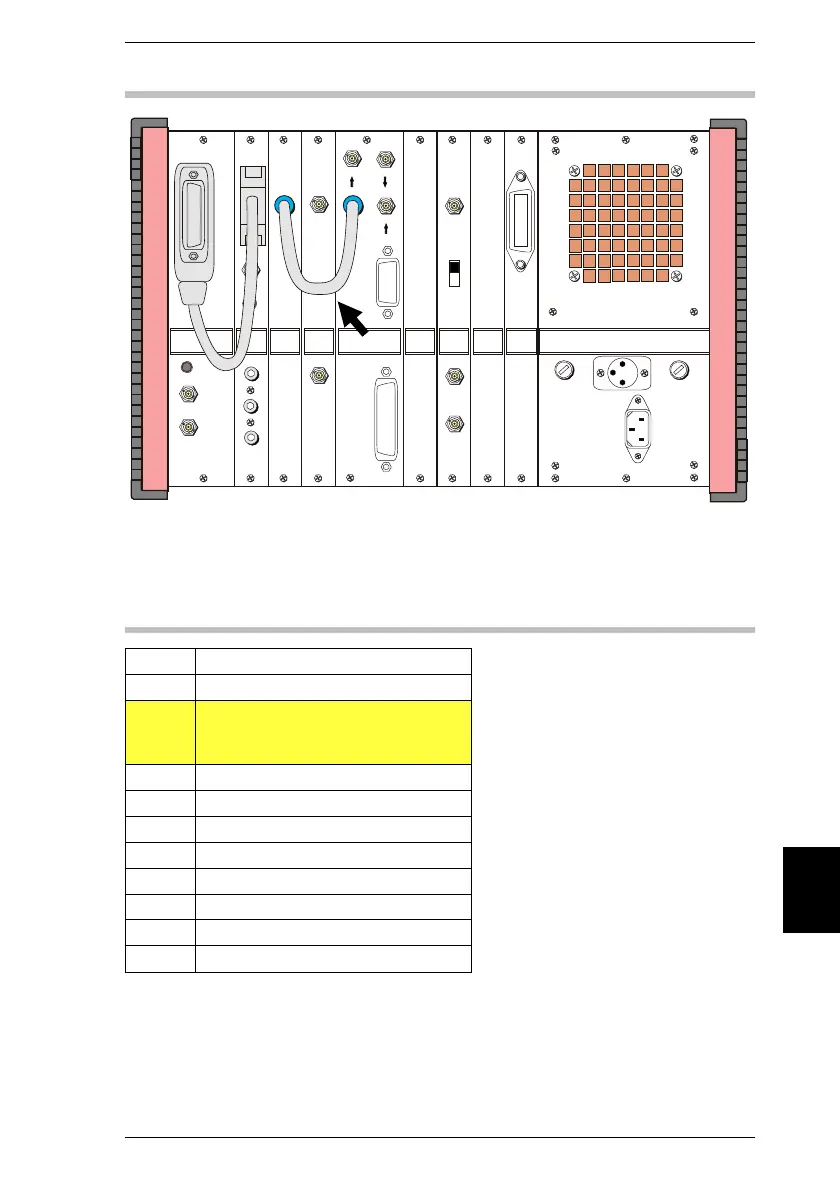
Fig. 10.27: If sockets Bu 103 are not connected as marked here, no call setup is possible
between mobile and test set. All other sockets of D-AMPS unit are irrelevant for testing
IS-136 mobiles.
Slot Unit
1 AF DETECTOR
2 MOD GENERATOR B or
OPTION CARD or
CONTROL INTERFACE (A/B/C/D)
3 IF UNIT with/without Tracking
4 MOD GENERATOR A
5/6 D-AMPS UNIT
7 SLAVE COMPUTER
8 DATA MODULE
9 MONITOR CONTROL
10 HOST COMPUTER
Internal D-AMPS DUPLEX UNIT
Equipment configuration required for
testing IS-136 mobiles. Slot 2 can hold
any of the options mentioned.
The following may not be included at
the same time:
ACPM option
SSB option
GSM module
RS232/Centronics interface
10
Back Panel IS-136 MS
10-55