11
Peugeot 207
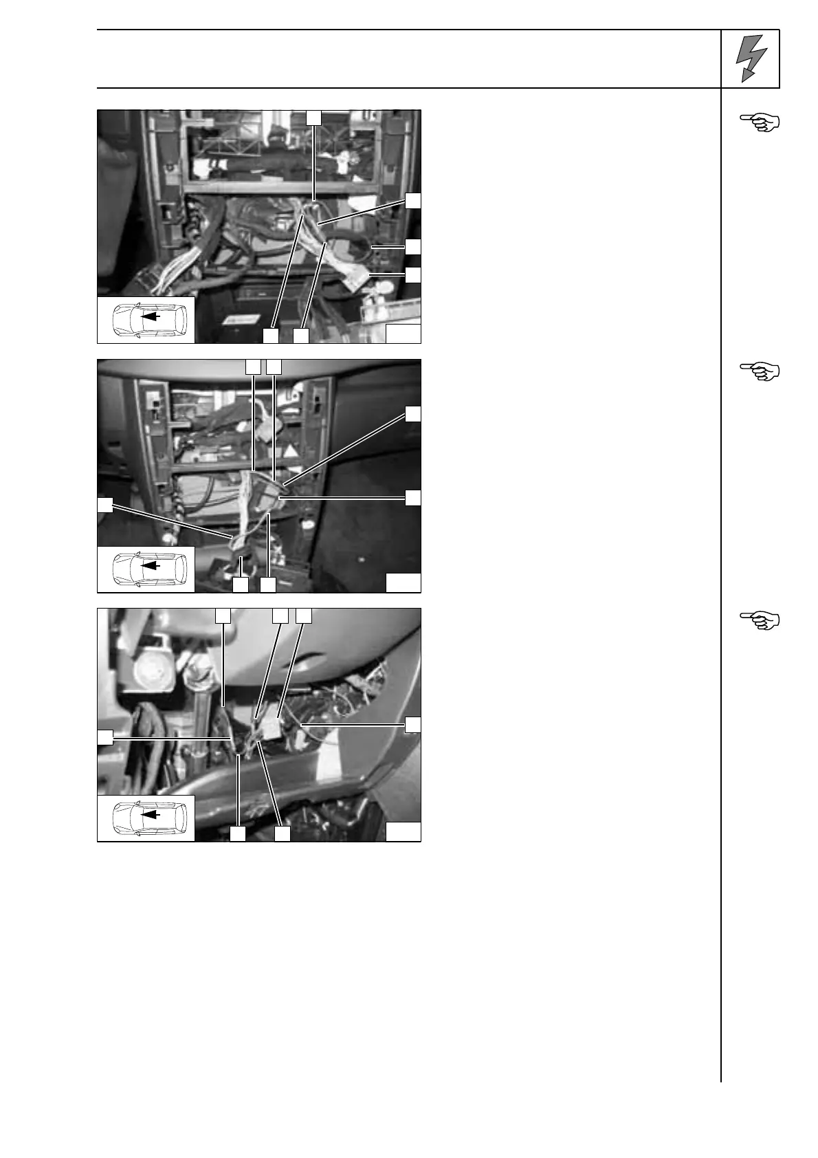
Connection to 18-pin connector 18V NR 4
from the air conditioning control.
Connect with enclosed blue butt connector 2
according to the circuit diagram.
1 Red (rt) wire to K3.1/86
3 Red (rt) wire to IPCU terminal 15
5 Grey (gr) wire to connector 18V NR
6 Grey (gr) wire from terminal 15
Connect-
ing
terminal 15
for K3.1
and IPCU
Connection to 18-pin connector 18V NR 5
from the air conditioning control.
Connect with enclosed red butt connectors 2
[2x] according to the circuit diagram.
1 Pink (ro) wire from BSI1/6
3 Red (rt) wire from K3.1/87
4 Black (sw) wire from K3.1/30
6 Pink (ro) wire to connector 18V NR/18
Connect-
ing relay
K3.1
Connection to the green 6-pin connector 6V
VE 3from the blower controller.
Connect with enclosed red butt connectors 2
[2x] according to the circuit diagram.
1 Red (rt) wire from IPCU/E
4 Black (sw) wire from IPCU/A
5 Red (rt) wire to connector 6V VE/6
6 Red (rt) wire to connector 40V BE/39
Connect-
ing the
blower
controller
11
1
5
2
3
6
4
12
1
5
4
2
2
6
3
13
1
6
4
2
5
2 3
 Loading...