www.weg.net
28 l Automatic Voltage Regulator – AVR-A-OPT-06
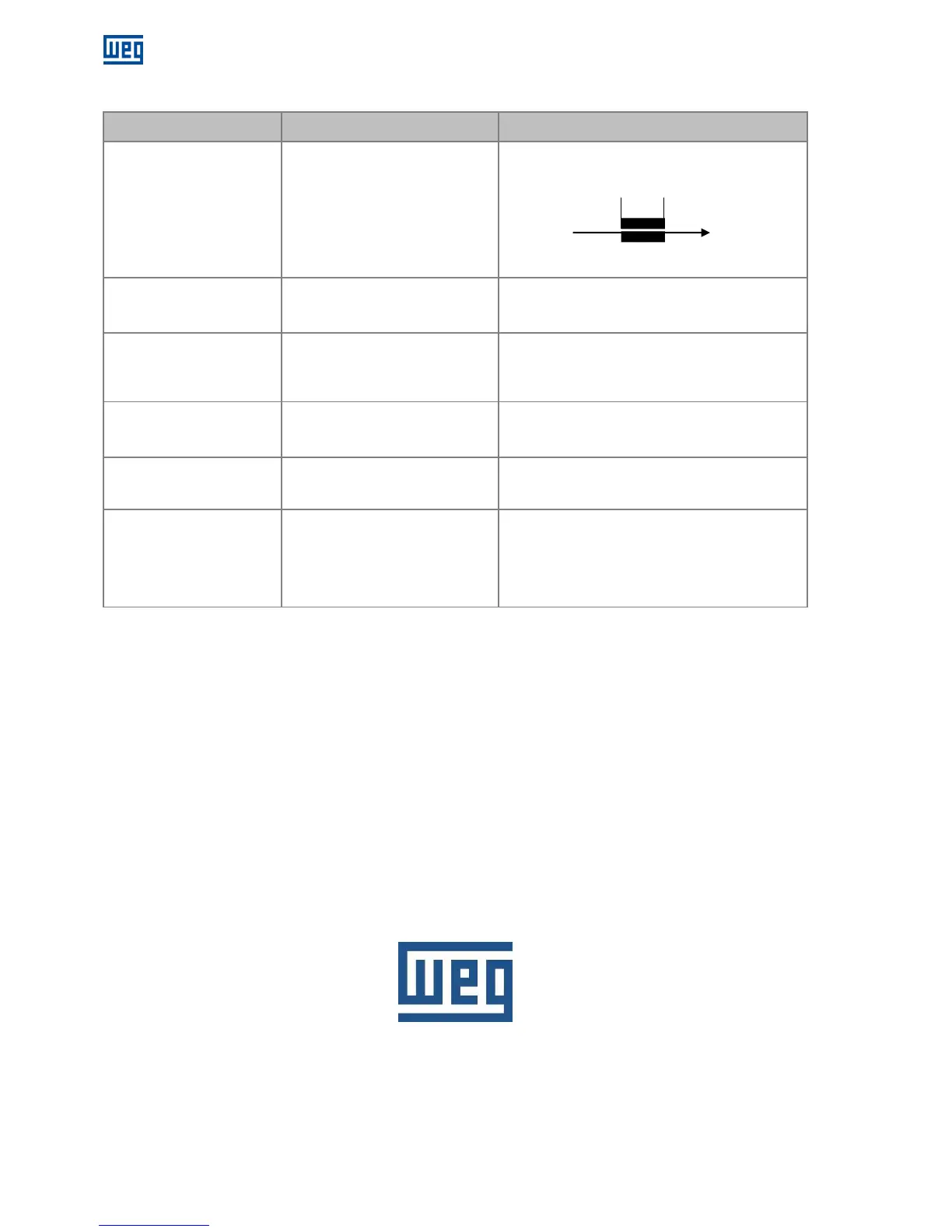
17 TROUBLES, CAUSES AND CORRECTIVE ACTION
Problems Causes Corrective Action
There is circulation of reactive
power between alternators
when operating in parallel.
Phases sequence (R-S-T)
incorrectly connected.
CT connections are inverted.
Droop adjustment excessively low.
Connect phase sequence correctly.
Correctly polarize the CT in the phase shown below:
Increase droop adjustment, rotating trimpot Drp
clockwise.
Generated voltage decreases
when load is applied, and it
doesn’t return.
Dropping speed of the driving
machine.
U/F Limiter engaged.
Correct speed regulation.
•Adjust U/F Limiter by rotating trimpot U/F
counterclockwise.
Alternator voltage does not
increase.
Residual voltage excessively low.
Terminals F (+) and F (-) are
inverted.
•With the regulator switched- on, use external battery
(12Vcc) to force excitation (*).
Invert F (+) and F (-)
Generated voltage oscillates
at no load.
Dynamic not well adjusted.
Alternator excitation voltage
excessively low.
Adjust trimpot Stb;
Insert 15/200W resistor in series with field.
Voltage oscillates at a specific
load point.
Third harmonic of the auxiliary coil is
high.
Eliminate auxiliary coil and proceed with the
connections according to the diagrams of page 17.
Voltage surges.
Lack of sensing.
Faulty electronic circuit.
Sensing voltage incompatible with
regulator.
Check if alternator phases are present in the sensing.
If the regulator is encapsulated, replace it.
(*)Always use an external battery for diesel gensets where the neutral of the alternator is grounded.
18 PREVENTIVE MAINTENANCE
Periodical inspections of the equipment are required to ensure they are clean, dust and moisture free. It is essential that
all terminal and connections are kept free from corrosion.
19 WARRANTY
See the Installation and Maintenance Manual of the WEG alternator.
WEG Group - Energy Business Unit
Jaraguá do Sul - SC - Brazil
Phone: 55 (47) 3276-4000
energia@weg.net
www.weg.net
P1

 Loading...


