About the ECW500 .
16 | ECW500
4 ABOUT THE ECW500
4.1 ABOUT THE MANUAL
This manual contains information for the operation, configuration and start-up of the product ECW500
applicable to both synchronous machine operating as a motor (synchronous compensator) and as a generator.
The main electrical features, standard functions and application of the ECW500 will be presented.
Due to the wide range of functions of this product, it may be used in applications different from those presented
hereby. Neither does this manual aim at presenting all the possible applications of the ECW500, nor can the
manufacturer take any liability for the use of the converter which is not based on this manual.
This manual can also be downloaded at WEG website www.weg.net.
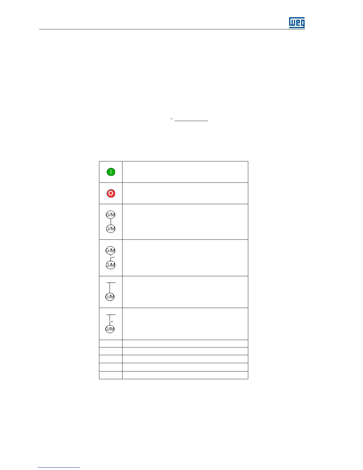
4.1.1 Symbols Used
This section presents the definition of the symbols used in this manual to identify features of the ECW500.
Rectifier: Input circuit of the inverters which converts the AC input voltage into DC. It is formed by power
diodes.
DC link: Intermediate circuit of the ECW500; continuous voltage obtained by rectifying the alternate power
supply or through external source; supplies the IGBTs switches used to control the excitation of the
synchronous machine.