Functional Description .
46 | ECW500
voltage at the machine terminals follow the slope configured, as shown in Figure 6.15. In the other operating
modes, the underfrequency condition is announced, but the reference (for excitation current, reactive power or
power factor) is not changed.
The equation below shows how the portion that actuate on the reference of the voltage control mode is
calculated.
In which:
V
UF
it is the portion which is added to the voltage reference.
V
rated
is the rated voltage of the synchronous machine configured on the ECW500 (30058).
f
rated
is the rated frequency of the synchronous machine configured on the ECW500 (30062).
f
knee
point is the frequency configured on the ECW500 from which the limiter starts to actuate (30118).
f
measured
is the frequency measured by the ECW500 (40010).
K
UF_ knee
point is the slope constant of the curve of the U/F (30120).
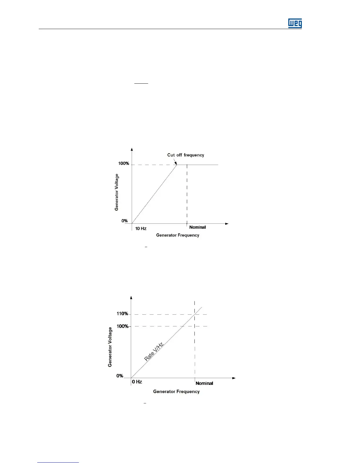
Figure 6.15 U/F curve of the underfrequency limiter
The V/Hz Underfrequency type limiter has the purpose of maintaining constant the ratio between the voltage
and frequency. V/Hz is the ratio of rated voltage and rated frequency multiplied by the slope constant (drop)
configurable in the 30120 parameter of the ECW500. When the ratio V/Hz measured exceeds the set value, the
limiter operates adding or subtracting a value to the main control loop reference with the objective of keeps the
V/Hz value ratio constant. The Figure 6.16 shows a typical V/Hz limiter operation curve.
Figure 6.16 V/Hz curve of the underfrequency limiter