5
DETAILED PARAMETER DESCRIPTION
Table 5.36: Dead Zone
P0233 Function
0
Inactive
1
Active
P0234 - Analog input AI1 gain (unipolar MVC4 board)
Adjustable range: 0.000 to 9.999 Factory setting: 1.000
Acesso: Menu → Configurations → I/O → Analog inputs
Description: AI1’ = -2 V, means the motor will spin in the opposite direction with a reference in module equal to
2 V.
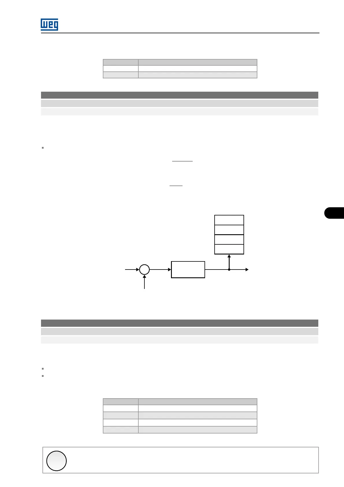
The internal values AI1’, AI3’, AI4’ and AI5’ are the result of the following equation:
AIx’ = (AIx +
OFFSET
100
× 10 V) × Gain
Example: AI1 = 5 V, OFFSET = -70 % and Gain = 1,00
AI1’ = (5 +
(-70)
100
× 10 V) × 1 = -2 V
AI1’ = -2 V, means the motor will spin in the opposite direction with a reference in module equal to 2 V.
GAIN
AI5' - P0028
AI4' - P0021
AI3' - P0020
AI1' - P0018
AIx'
Reading
+
+
AIX
AI1 - P0235
AI3 - P0243
AI4 - P0246
AI5 - P0723
OFFSET (P0236, P0244, P0247, P0724)
(P0234, P0242, P0245, P0722)
Figure 5.29: Block diagram of the analog inputs AI1, AI3, AI4 and AI5
P0235 - AI1 Signal Type
Adjustable range: 0 to 3 Factory setting: 0
Acesso: Menu → Configurations → I/O → Analog inputs
Description:
When current signals are used at AI1 input, put S2.A on the MVC4 control card in the “ON” position.
For options 2 and 3 inverse reference is attained, that is, maximum speed is obtained with minimum reference.
Table 5.37: AI1 Signal Type
P0235
Function
0
(0 to 10) V/(0 to 20) mA
1
(4 to 20) mA
2
(10 to 0) V/(20 to 0) mA
3
(20 to 4) mA
✓
NOTE!
This parameter can be changed only with the motor stopped.
MVW3000 | 5-45