5
DETAILED PARAMETER DESCRIPTION
Scalar control mode:
I
tm
rated
= Rated inverter torque current.
P0010 - Inverter output power
Acesso: Menu → Status → Measurements → Power
Description:
It indicates the calculated value of the inverter output power in kW.
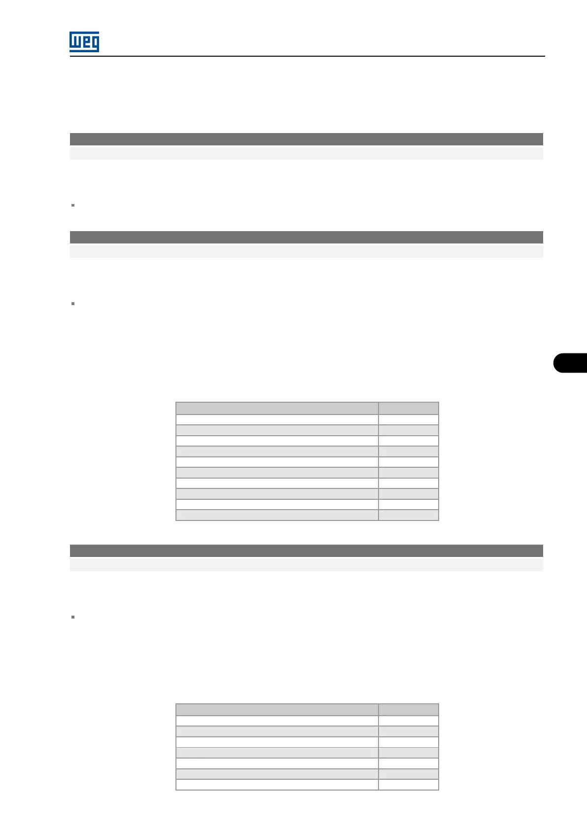
P0012 - Digital inputs DI1 to DI10 status
Acesso: Menu → Status → I/O → Digital
Description:
It indicates, on the Graphic HMI, the status of the 8 digital inputs of the MVC4 control board (DI1 to DI6, DI9,
DI10) and of the 2 digital inputs of the optional board (DI7, DI8) through the letters A (Active) and I (Inactive), in
the following order:
DI1, DI2, ... ,DI7, DI8, DI9, DI10
Table 5.2: Digital inputs DI1 to DI10 status
Description
Bit
DI8 Bit 0
DI7
Bit 1
DI6
Bit 2
DI5 Bit 3
DI4
Bit 4
DI3 Bit 5
DI2
Bit 6
DI1
Bit 7
DI9 Bit 8
DI10 Bit 9
P0013 - Digital outputs DO1 to RL5 status
Acesso: Menu → Status → I/O → Digital
Description:
It indicates, on the Graphic HMI, the status of the 2 digital outputs of the optional board (DO1, DO2) and of the
5 relay outputs of the MVC4 control board through the letters A (Active) and I (Inactive), in the following order:
DO1, DO2, RL1, RL2, RL3, RL4, RL5
Table 5.3: Digital outputs DO1 to RL5 status
Description
Bit
RL5
Bit 1
RL4
Bit 2
RL3 Bit 3
RL2
Bit 4
RL1
Bit 5
DO2
Bit 6
DO1
Bit 7
MVW3000 | 5-5