67 of 76
TECHNICIANS manual
ENGLISH
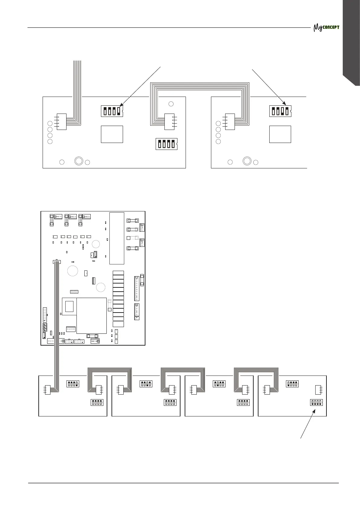
16.3 DISPLAY control unit diagram
ON1234
DIP2
CN40
CN41
CN41
CN40 CN41
CN41
ON1234
DIP1
ON1234
DIP2
CN40
ON
1
234 ON
2
134 ON
3
124 ON
4
123
DIP2
ON1234
DIP1
CN40 CN41
DIP2
ON1234
DIP1
CN40 CN41
DIP2
ON1234
DIP1
CN40 CN41
DIP2
ON
1234
DIP1
GRP1 Display
GRP1 Display GRP2 Display GRP3 Display GRP4 Display
GRP2 Display
Control unit
Wiring diagram of the DISPLAYS
On DIP2, set the switch corresponding
to the group of reference to ON
On DIP1 of the last DISPLAY
set all switches to ON