TECHNICIANS' manual
- English -
43 di 52
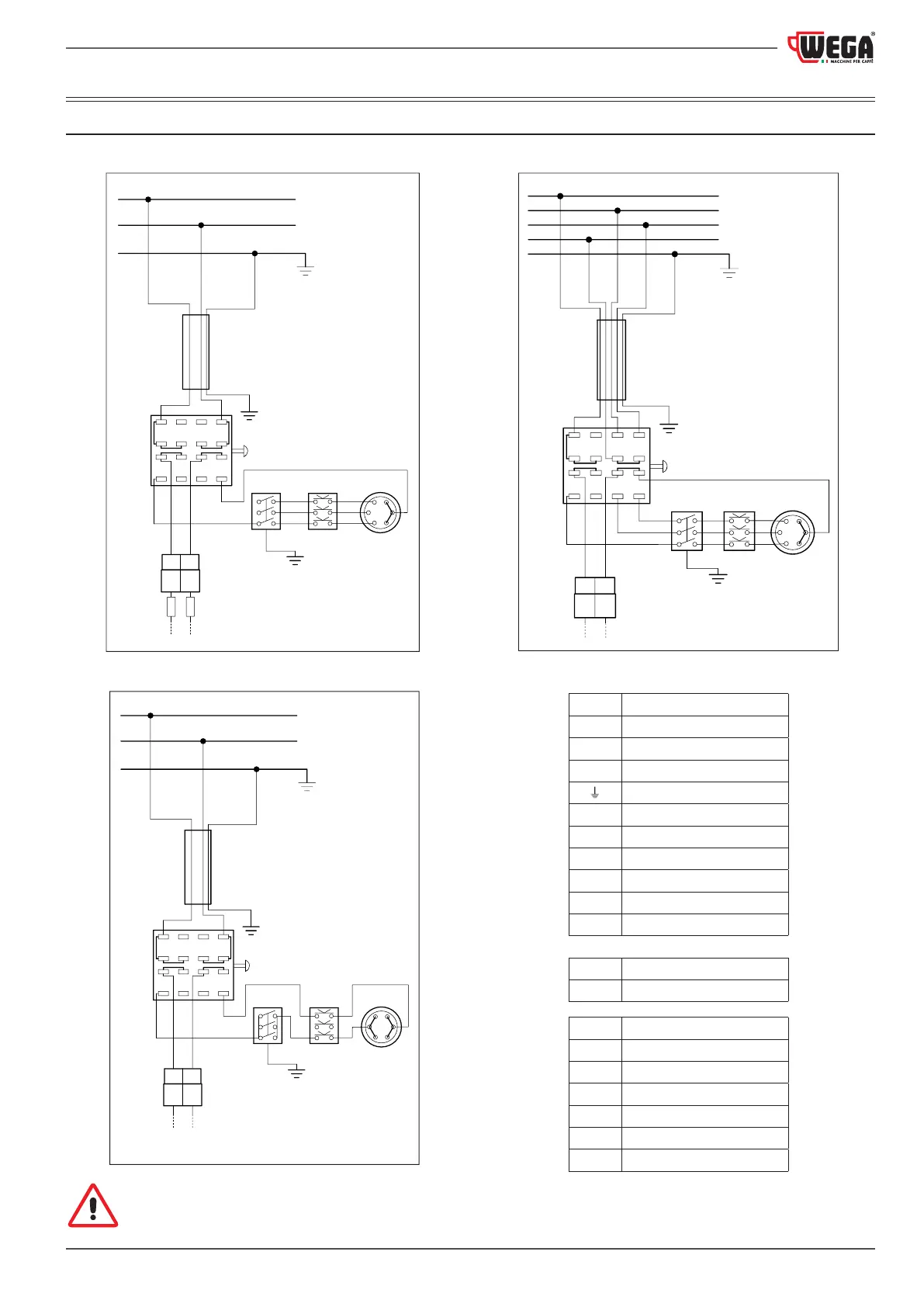
12. WIRING DIAGRAMS
12.1 ELECTRIC MAINS connection
VERSION UL 3-POLE CABLE (Phase+Neutral+Earth)
PR SA
CO
CT
RE
BK
WH GNYE
CAB
RD
WH
BK
BK WH
BK
13 9 5
1
3
71115
16 12 8
4
2
61 0
14
N
R
F4 F5
VERSION EU 3-POLE CABLE (Phase+Neutral+Earth)
PR
SA
CO
CT
RE
BK
WH GNYE
CAB
RD
WH
BK
WH WH
WH
BK
13 9 5
1
3
71115
16 12 8
4
2
61 0
14
N
R
VERSION EU 5-POLE CABLE (3 Phases+Neutral+Earth)
PR SA
CO
CT
RE
BN
BKBU GNYEGY
CAB
BN
BN
BU
BK
RD
BU
13 9 5
1
3
71115
16 12 8
4
2
61 0
14
S
N
T
R
R Phase
S Phase
T Phase
N Neutral
Earth
CAB
Power cable
CO Power switch
CT Connector
PR Pressure switch
RE Electric heating element
SA Safety thermostat
F4 Fuse 15 A UL
F5 Fuse 15 A UL
BK Black
BN Brown
BU Blue
GY Grey
GNYE Green-Yellow
RD Red
WH White
To correctly connect the machine to the electric mains, please refer to the information provided on the nameplate
(see the example in paragraph
2.8 on page 14).