Do you have a question about the WEIHONG NCStudio V12 and is the answer not in the manual?
| Operating System | Windows |
|---|---|
| Real-time Monitoring | Yes |
| Simulation Function | Yes |
| Interpolation | Linear, Circular |
| Compatible Machines | CNC Routers, Milling Machines |
| Interface | PCI |
| Supported File Formats | G-code |
| Language Support | Multiple languages |
| Control Mode | Position Control |
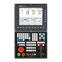
| Control System | WEIHONG NCStudio V12 |
Details hardware and software components for system setup.
Illustrates the physical connections between system components.
Provides detailed wiring schematics for Lambda 5M and EX31A1 terminal boards.
Step-by-step guide for installing the necessary camera driver software.
Instructions for installing or re-installing the NcStudio V12 CCD control system software.
Describes various functional windows for machine control and monitoring.
Displays machine and workpiece coordinate systems for precise positioning.
Visualizes the real-time machining path of the tool.
Allows setting workpiece and public offsets for programming and movement.
Lists local and USB program files, and access to program wizards.
Guides defining the workpiece origin by finding the center point.
Enables execution of CCD setup operations and adjustments.
Displays and allows modification of all system parameters.
Shows status and description of system input/output ports.
Configures machine origin (datum) for absolute positioning.
Explains the function of operating buttons and F-key shortcuts for machine control.
Area for detecting communication status between software and hardware.
Area to view current tool information and access compensation parameters.
Controls axis movement and selects feed modes for manual operation.
Guides setting camera parameters like exposure and gain for optimal imaging.
Procedures for debugging CCD camera and machine tool after installation or repair.
Steps to measure and set the camera's focal length for clear imaging.
Process to determine the pixel-to-displacement ratio for accurate measurements.
Method to measure and compensate for the spatial offset between spindle and camera.
Settings for aligning the CCD camera with the workpiece features.
Configures the image matching mode based on feature point similarity.
Details methods for shooting single, two, three, or four points for feature detection.
Guides creating and refining templates for feature point extraction.
Covers auxiliary operations like display modes, array machining, and compensation.
Options for displaying live or captured images from the camera.
Instructions for performing array machining operations.
Steps to enable or disable the CCD system for machining.
Sets the workpiece origin using the CCD center for specific shooting methods.
Sets safety offsets to prevent damage during machining of small or tiled areas.
Compensates for workpiece tilt by adjusting offsets for each station.
Adjusts for deviations between the ideal and actual workpiece dimensions.
Applies Z-axis depth adjustments for replaced workpieces in array machining.
Manages tool length compensation automatically to increase tool reuse.
Explains potential errors in the CCD and their causes, like pixel accuracy.
Discusses workpiece error determination based on shooting point accuracy.
Steps to troubleshoot errors by checking magnification and camera installation.
Procedure to test camera and lens installation for stability and accuracy.
Explains how incorrect shooting point positions affect machined workpiece quality.
Highlights key differences between simulation and real machining processes.
Defines requirements for selecting unique feature points for magnification measurement.