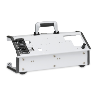
Front
3
VENTIlogic LS:
Connection for patient's exhaled air with double patient circuit with patient valve.
VENTIlogic plus:
Opening is not used with VENTIlogic plus.
4
Jack: electrical connection for oxygen sensor; max. 100 mV DC
5
Connection: pressure measuring tube (marked blue). Therapy pressure 0 - 50 hPa
(only for patient circuit with patient valve)
6
Connection: control tube for patient valve 0 - 50 hPa (only patient circuit with
patient valve)
7
Device outlet port: outlet for exhaled air at 0 - 45 hPa with patient circuits with
patient valve, 0 - 40 hPa with leakage ventilation
8
Device outlet port: only patient circuits with a diameter of Ø 15 mm - 22 mm are
permitted.
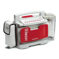
Right-hand side
9
Connection for optional attachments, e.g. Analog box D/A;
max. current delivery at 5 V: 50 mA
10
Connection for specialist staff to set therapy parameters using VENTIviews; max.
current delivery at 12 V: 50 mA
11
SD card slot
12
Replaceable battery
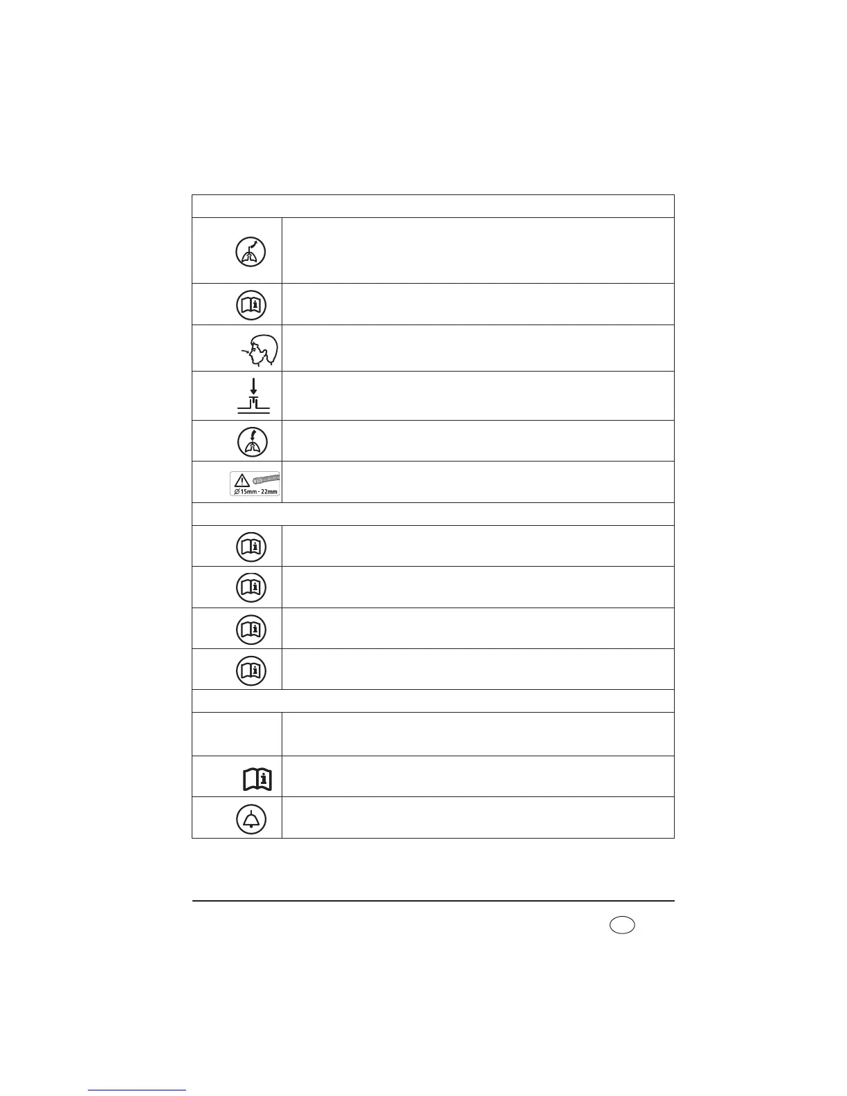
Rear
13
Connector for power supply input 115/230 V AC; 50/60 Hz
14
Follow instructions for use
15
Connection for remote alarm: connection for nurse call system and VENTIremote
alarm remote alarm case. Breaking capacity: 60 V DC/2 A; 42 V AC/2 A