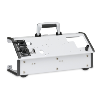
2. Plug the oxygen sensor (1) and air management
adapter into the T-adapter (3).
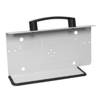
3. Plug the T-adapter (3) onto the device outlet port (5).
4. Connect the sensor (1) to the oxygen measuring jack
(4) with the aid of the cable.
5. Connect the patient circuit - with a bacteria filter if
required - as shown in the illustration.
6. Calibrate the oxygen sensor (see “7.3 Calibrate
oxygen sensor (only valve ventilation)” on page 78).
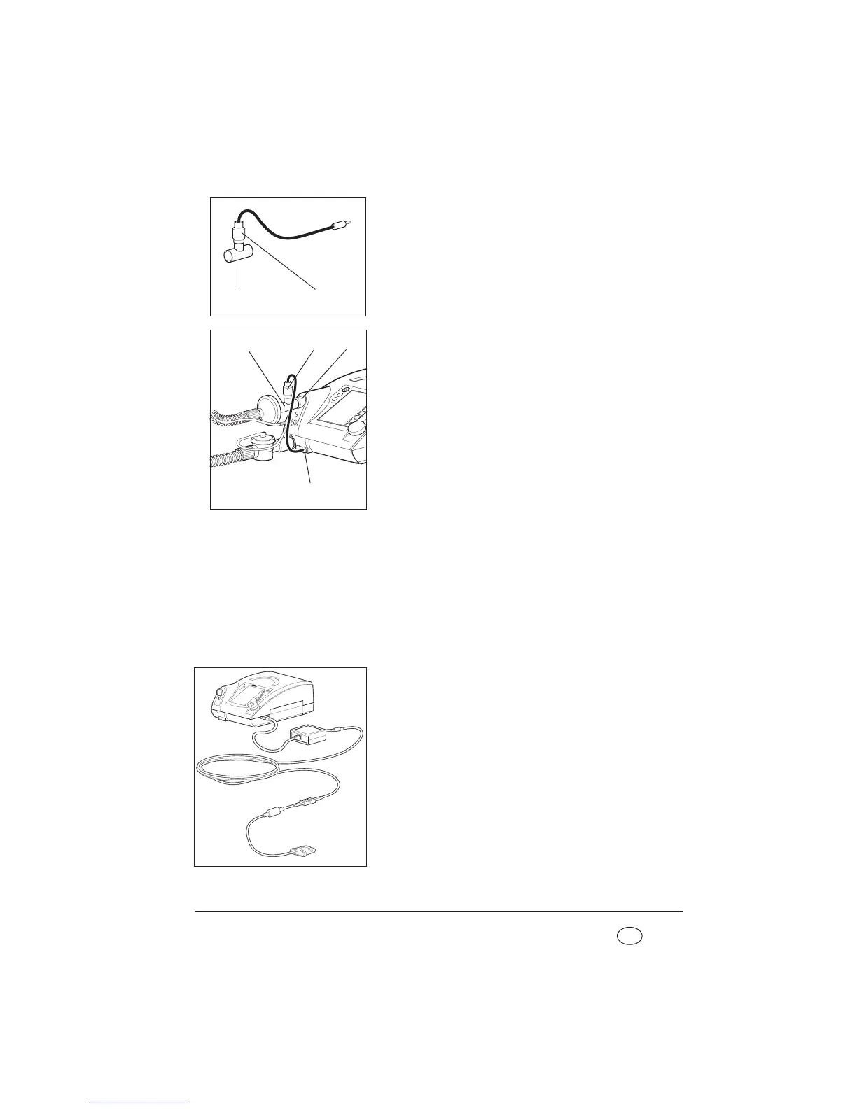
4.7.3 Measuring oxygen saturation and pulse
Using the optional, non-invasive SpO
2
module, oxygen saturation levels (SpO
2
), heart rate
and alarms can be measured, showed on the display of the device and saved to the SD-
card.
The SpO
2
and heart rate parameters can each be monitored using upper and lower alarm
limits, synchronized using VENTIviews software and represented on a computer screen
with other ventilation data.
1. Connect the SpO
2
module to the serial interface on the
device. The displays and alarms for oxygen saturation
and pulse rate are activated via this.
2. Attach the SpO
2
sensor onto the fingertip and wait
until the measured values are shown on the display.
3 1
3
1
5
4