Rotary indexing ring TR
Maintenance
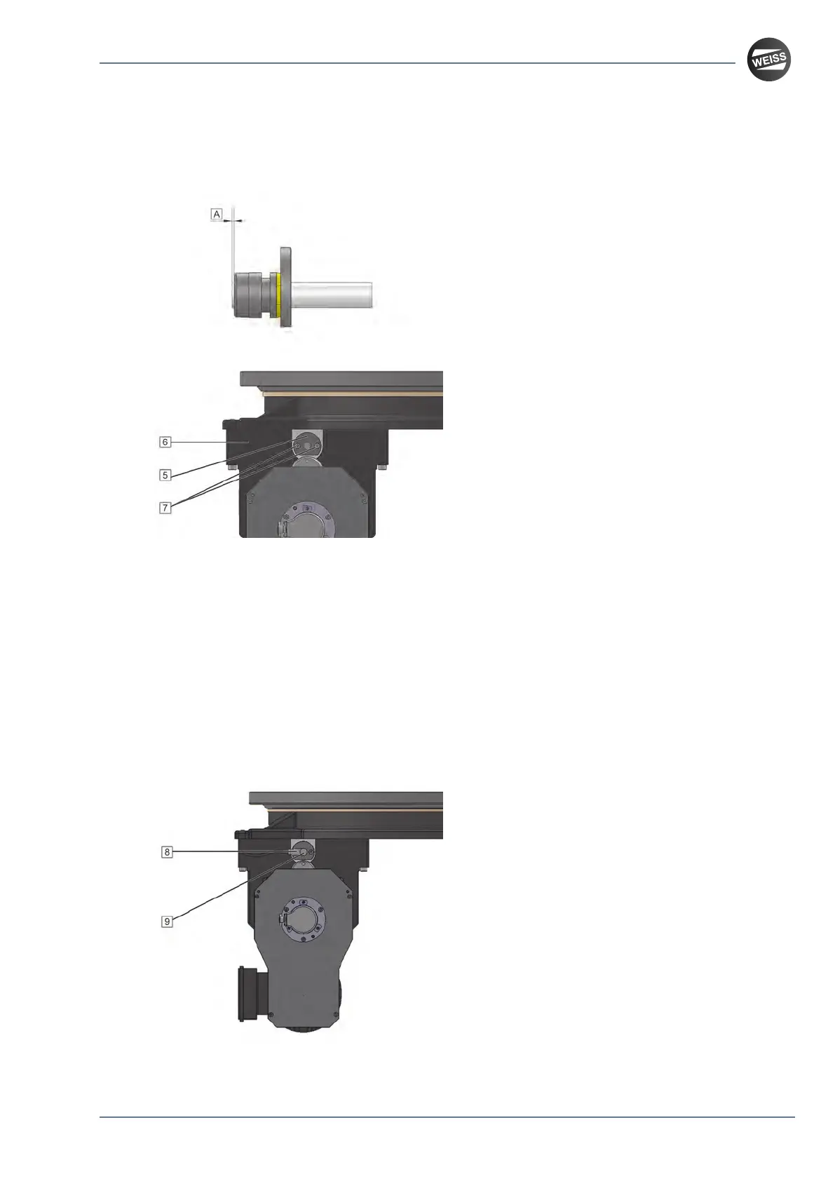
The head of the inductive sensor must pro-
trude from the limit switch bushing by approxi-
mately 1 mm (dimension [A]).
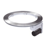
5. Fit the limit switch bushing [5] with the
inductive sensor into the cam housing [6].
6. Tighten the screws [7].
7. Manually turn the inductive sensor
clockwise into the limit switch bushing
until the head of the inductive sensor is in
contact with the position cam.
8. For TR0750A:
Manually turn the inductive sensor
counter-clockwise by three thirds of a
revolution out of the limit switch bushing.
P
The switching distance amounts to
approximately 0.5 mm.
9. For TR1100A, TR1500A, TR2200A:
Manually turn the inductive sensor
counter-clockwise by two revolutions out
of the limit switch bushing.
P
The switching distance amounts to
approximately 2 mm.
10. Secure the inductive sensor with the nut.
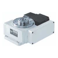
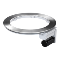
11. Plug the connector [8] onto the inductive
sensor [9].
12. Remove all tools and equipment.
13. Perform a test run.
Mounting instructions_062019_4.0_en
75 / 79