Welch Allyn, Inc.
14 SureTemp
®
Model 670/SureTemp 4
®
Model 675
Probe Enhancements
The Model 670 and Model 675 series thermometers have the capability to detect probe type - oral vs. rectal.
This allows the oral temperatures to be as fast as possible (10 seconds in the 670 and 4 seconds in the 675)
by using different operating modes based on probe type. Rectal probes give a Normal mode temperature in
about 15 seconds for both models. This probe type recognition also allows the use of minor differences in
prediction parameters tailored to the temperature taking site to help increase speed over previous products.
The probe type is communicated to the thermometer by the use of shorting jumpers between ground and
two of the probe connector contacts.
In addition to the probe type enhancements, Model 670 and Model 675 probes have been improved for
thermal time constant (speed of response).
Model 675 oral probes incorporate a warming resistor in the tip to pre-warm the probe before placement in
the mouth, thus speeding response even further.
Probe Switch
The probe switch (S1) is activated by the probe shaft when the probe is installed or removed from its storage
channel. Placing the probe into the channel, pulls processor pin 23 high via R24. When the probe is
removed, this line is pulled low. This signal is also routed to test connector J3 pin 7 to allow automated
testing of this function during factory test. R24 allows this line to be pulled high or low at J3 during factory
test regardless of the actual switch position.
HINT/CAUTION: For the technician, J3 serves as a convenient set of “test points” to monitor proper
operation of all user switch functions, BUT BE CAREFUL WITH STATIC DISCHARGE! J3 TIES DIRECTLY
TO CMOS PROCESSOR INPUTS WHICH ARE EASILY DAMAGED BY STATIC DISCHARGE. FOLLOW
PROPER HANDLING TECHNIQUES.
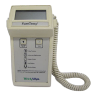
Monitor Mode
The Monitor mode is selected manually by the Normal/Monitor mode slide switch (S3) on the top of the
instrument. This switch ties pin 10 on the processor (U2) either high or low for Normal or Monitor modes
respectively. This signal is routed through R14 and is also taken to the test connector J3 pin 4 to allow
automated testing of this function during factory test. R14 allows this line to be pulled high or low at the test
connector regardless of the switch position.
The actual probe temperature, as determined by the A/D conversion electronics, appears directly on the
liquid crystal display which is driven by the integral LCD driver in the microprocessor. See the
Temperature
Measurement and Display
section on page 16 for a description of the A/D operation.
The displayed temperature range (for any mode) is limited to 28.9
°
C to 42.2
°
C (84.0
°
F to 108.0
°
F).
Normal Mode, Model 670
The shape of the rising temperature curve is monitored and a continuously computed correction factor is
added to the actual probe temperature. The temperature cycle is terminated and the temperature is
displayed when the predicted temperature remains stable.
If the thermometer does not detect a rise of two degrees above ambient within 30 seconds of removing the
probe from its holder, it will automatically switch to Monitor mode.
 Loading...