Technical Manual
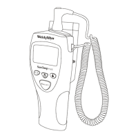
SureTemp
®
Model 670/SureTemp 4
®
Model 675 19
Once the probe has been brought near 33.9
°
C (93
°
F), the pulse widths are reduced to maintain this
temperature. This is when the display switches from the all segments display test to “OrL” indicating that the
unit is ready for placement in the mouth.
Note:
Do not confuse this with the displays during probe characterization, where “OrL” is indicating that
characterization is in progress with the probe in the holder.
R20 and R21 in combination with R23 serve as pull down resistors ensuring that the processor feedback
lines (U2 pins 15 and 16) go low immediately upon warmer component shut off. L1 and C7 serve as RFI
suppression components.
Note:
On Model 670, some of the components in the warmer circuit may be installed but they are not used.
Q7 is NEVER installed at the factory and should never be installed on Model 670. Installation of Q7 will NOT
activate the warmer on Model 670 and will cause a malfunction error code to result, inhibiting further use of
the instrument.
EEPROM
U3 is an Electrically Erasable Programmable Read Only Memory (EEPROM) incorporating a serial data
communication interface with the microprocessor. Data is clocked synchronous with the “serial clock” input
on pin 2. Data into the EEPROM goes into pin 3. Data out of U3 comes out on pin 4. Pin 1 is the chip
select line. Pin 5 is the ground pin but is tied to a processor port line. This allows power to be saved by
driving all EEPROM pins to the positive supply which reduces power consumption to zero for this part. The
EEPROM is therefore only turned on when needed, which is only during power up routines. Most of the time
the EEPROM data is stored in RAM, which remains even when the processor enters sleep mode (as long as
battery power is available). Therefore, unless a software error has occurred, the EEPROM is only read upon
installation of new batteries. The EEPROM is downloaded initially at the factory with operating parameter
data giving the thermometer most of its operating characteristics such as factory test system parameters,
Normal mode prediction parameters, warmer control parameters, and numerous miscellaneous parameters
setting operating temperature limits, times, warning levels, etc. The EEPROM cannot be changed in the
field.
Liquid Crystal Display
The LCD has 4 backplane lines (U2 pins 2-5) and 24 segment lines (U2 1, 57 - 72, 74 - 80). The LCD fluid
thresholds require a regulated set of voltages at 1.2, 2.4, and 3.6 volts. These are supplied to processor
pins 6, 7 and 8 from the diode stack D1, D2, D3, D4, D5 and related components Q3, R4 and R17. Circuit
operation is initiated by the processor pulling pin 49 low. This draws the emitter of Q3 low and thus the base
of Q3 to .6 volts above ground. This voltage across R4 establishes a current through the diode stack. Any
change in power supply voltage is absorbed to a great extent by R17 and the Q3 collector connection
keeping the voltages across the diodes relatively constant.
The LCD glass is electrically tied to the display PCB via two elastomeric connectors sandwiched and
compressed between the glass and the PCB by the frame. This assembly, if taken apart, cannot be
reassembled without replacing the frame.
Backlight/Temperature Recall
The backlight is an electroluminescent style flat panel lamp residing directly under the LCD.
An oscillator is required to convert battery DC voltage to an AC voltage of about 80 volts and 300 Hz.
 Loading...