Technical Manual
SureTemp
®
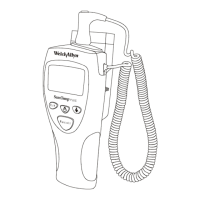
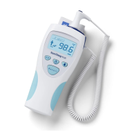
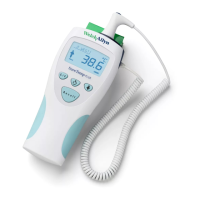
Model 670/SureTemp 4
®
Model 675 17
the discharge current but constitutes a very small constant DC resistance so it has no effect on results. Its
only purpose is for RFI suppression. C3, C10, C11, C12 and C13 are also only for RFI, and ESD purposes.
In Monitor mode a calibration cycle, where each of the fixed resistors is measured by the A/D function, is
performed once every second. In Normal mode a calibration cycle is performed once at the beginning of the
temperature prediction process.
Battery Voltage Reading
Battery voltage reading capability has been added over previous products providing necessary information to
the probe warming function and also providing the enhanced two stage low battery indicator.
When not in use, the BATT AD SELECT line (U2 pin 41) is held low. This keeps diode D9 reverse biased
and thus R28 has no effect on the normal A/D function during temperature measurements.
When battery voltage is to be read, this line is brought high by the processor (to whatever the battery voltage
happens to be). This voltage across R28 establishes a current flow. (The common point of R28 with the
other resistors is at 0.6 volts - because Q11 base is at 1.2 volts). This current flowing through R28 increases
the A/D pulse width since this much current is
not
needed from C2. R5 is always selected for battery voltage
reading since it normally produces the shortest pulse. If battery voltage is low, the current supplied via R28
is low and therefore the pulse width is lengthened only slightly. If the battery voltage is high, the pulse width
is lengthened more. Knowing the standard pulse width from R5 allows the instrument to relate this
lengthening of pulse width to the supply voltage.
A/D Power Control
When A/D conversions are not needed, power is saved by shutting down U1 via the A/D PWR line on U2 pin
56. R27 serves as a current limiting resistor and establishes the low power draw for U1’s internal current
sources.
This A/D Power line is also routed to R11 and R13 for probe detection. This provides a power saving
function so supply current is not drawn through these resistors when probe detection is complete.
Probe Detection
Upon power reset or when a new probe is first installed, the thermometer performs a probe initialization
process. Probe type is first detected and then if it is a Model 675 and an oral probe, its warming
characteristics are determined. Model 670 thermometers do not warm probes so warming characteristics
are not tested on any type of Model 670 probe. No rectal probes are warmed, so warming characteristics
are not tested in either instrument on these probes.
The instrument keeps track of whether a probe is installed or not. This is accomplished by the fact that to
unplug a probe, the shaft must first be withdrawn from the storage channel. This wakes up the thermometer
which then turns on A/D power. This activates the probe type lines U2 pins 17 and 18 via R11, R12, R13
and R25. When the probe connector is removed, these lines are pulled high and a “no probe” logic is
detected. (The Cal Key is also “no probe” logic so the software upon seeing no probe actually reads the
probe resistance and if it falls well outside the Cal Key value, determines that indeed there is no probe
attached.) Upon determining that the probe has been removed, a software flag is set in RAM indicating the
probe has been removed. (RAM contents are not lost when the processor “goes to sleep.”) With no probe
installed, the unit “goes to sleep” and turns off the clock and the A/D power line to save battery power.
 Loading...