Welch Allyn, Inc.
4 SureTemp
®
Model 670/SureTemp 4
®
Model 675
7
6
5
4
1 2
8
NORMAL MONITOR
•C•F
9
13
14
3
12
11
10
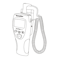
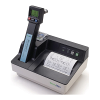
1. Probe cover box 8. Probe handle collar
2. Probe 9. Probe cover ejection button
3. Display 10. Probe cover storage well
4. Backlight/Recall switch 11. Fahrenheit/Celsius select switch
5. Timer switch 12. Normal/Monitor mode select switch
6. Display legends 13. Probe storage channel
7. Battery access door 14. Probe connector receptacle
FIGURE 1 - THERMOMETER DIAGRAM
Operating Controls and Components
Setup
If a problem is reported with an instrument, it is sometimes wise to investigate operation before the unit is
reset, but generally resetting the electronics is the recommended starting point in the process.
Instrument Reset/Self Tests
The batteries must be removed from the instrument to reset the internal microprocessor electronics. Follow
the battery removal instructions in the
Maintenance
section on page 11.
Because the instrument uses very little power, the reset will not occur immediately upon battery removal until
the capacitance of the circuit is discharged. To speed this discharge, after the batteries are out, press the
backlight or timer button for about 10 seconds. The electronics will now properly reset upon battery
installation.
Remove the probe from the probe storage channel and unplug the probe connector from the instrument by
pulling on the connector body. Do not pull on the cord.
 Loading...