Technical Manual
SureTemp
®
Model 670/SureTemp 4
®
Model 675 5
While watching the display, install the batteries per the instructions in the Maintenance section and observe
the power up self test.
The self test includes several internal microprocessor self tests, instrument electronics tests and the display
test. If there are internal electronics problems detected by the self tests, an error code (EX.X) will be
displayed. Refer to the
Error Codes
section on page 21 for an explanation.
The display test begins with each display segment individually lit in brief and rapid succession. At the same
time, the timer segments are incrementally turned on until all 30 are illuminated. Immediately after this, all
display segments are simultaneously illuminated briefly followed by a display of the software revision in this
instrument. The beeper also briefly sounds at the beginning of the tests, at the 15 second mark of the timer
and at the 30 second mark. If all is well from the power up self test, the display goes blank at this time (with
no probe installed.)
Note:
If a probe is installed during this power up time, different results will occur depending on whether the
probe is functioning properly or not. See the
Probe Initialization/Self Tests
section below for these tests.
At this point, there should be no probe connected to the instrument.
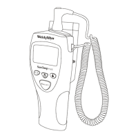
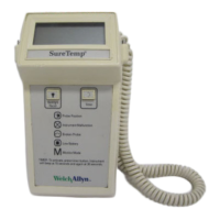
FIGURE 2 - THERMOMETER DISPLAY
If there is no display, any missing segments, or no beeper, refer to the
Troubleshooting
section on
page 22.
Probe Initialization/Self Tests
With a properly functioning instrument, the probe can be put through self test. The instrument will, if
functioning properly and a probe installed, initiate the probe self test during the instrument reset self test.
Proper instrument functionality should be verified first as described in the
Instrument Reset/Self Tests
section before a probe is installed.
With an instrument that passed the
Instrument Reset/Self Tests
section, install the probe connector first
(with the Diatek or Welch Allyn logo showing) and then fully insert the probe shaft into the storage channel.
Observe the display of the probe type. For Model 670, this probe type display will be very brief (less than 1
second.) For Model 675 Oral probes, the probe type will be displayed for about 10 to 15 seconds or possibly
even longer. Do not withdraw the probe. For Rectal probes, the display is brief. If the display does not
show “OrL” with an Oral probe plugged in, or “rEC” with a Rectal probe plugged in, there is a problem with
the probe, or the probe connector in the instrument. (For Model 670, if no display of probe type is shown, the
probe might be the wrong type for this thermometer and the instrument will not function.)
 Loading...