en
Installation and operating instructions Wilo-Stratos MAXO/-D/-Z 29
▪Electrical work: Electrical work must be performed by a qualified
electrician.
▪Installation/dismantling work: The installation/dismantling must be
carried out by a qualified technician who is trained in the use of the
necessary tools and fixation materials.
▪The product must be operated by persons who are instructed on
how the complete system functions.
Definition of “qualified electrician”
A qualified electrician is a person with appropriate technical educa-
tion, knowledge and experience who can identify and prevent elec-
trical hazards.
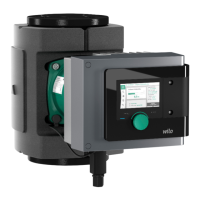
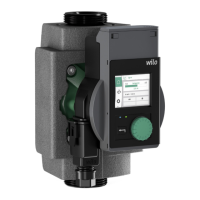
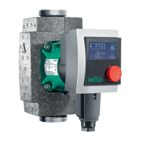
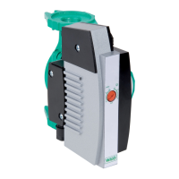
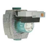
2 Description of the pump
The Stratos MAXO smart-pumps, in threaded pipe union or flange
connection versions, are glandless pumps with a permanent magnet
rotor.
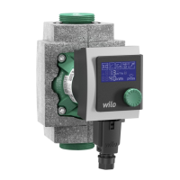
➜Fig.3 and 4
1. Pump housing
– 1.1 Direction of flow symbol
2. Motor
3. Control module
– 3.1 Graphical LC display
– 3.2 Green LED indicator
– 3.3 Blue LED indicator
– 3.4 Operating button
– 3.5 Back button
– 3.6 Context button
4. Optimised Wilo-Connector
5. Base module
– 5.1 LED display
– 5.2 Operating button of base module
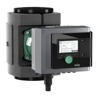
There is a control module (Fig.3, pos.3) on the motor housing,
which controls the pump and provides interfaces. Depending on the
chosen application or function, speed, differential pressure, tem-
perature or volume flow will be controlled.
For all control functions, the pump continuously adapts to the sys-
tem’s changing power requirements.
2.1 Type key
Example: Stratos MAXO-D 32/0,5-12
Stratos MAXO
Pump designation
-D
-Z
Single pump (without code letter)
Twin-head pump
Single pump for domestic hot water circulation
systems
32
Flange connection DN32
Screwed connection: 25 (RP1), 30 (RP1¼)
Flange connection: DN32, 40, 50, 65, 80, 100
Combination flange: DN32, 40, 50, 65
0.5 – 12
Continuously adjustable setpoint height
0,5: minimum delivery head inm
12: maximum delivery head inm
 Loading...