Do you have a question about the Wilo Stratos MAXO and is the answer not in the manual?
These instructions enable the safe installation and initial commissioning of the pump.
These instructions set out safety instructions for preventing personal injury and damage to property.
Personnel must be instructed and have read and understood the installation and operating instructions.
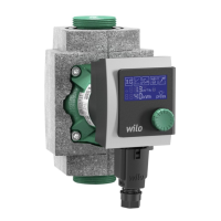
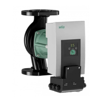
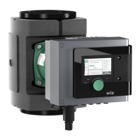
Explains the designation of the Stratos MAXO pump model based on its features and specifications.
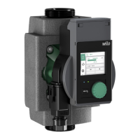
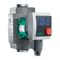
Details regarding pump housing, motor, control module, Wilo-Connector, and base module components.
Minimum inlet pressure required at the pump's suction port to avoid cavitation noises.
Defines the permitted applications and fluids for the pump circulation systems.
Lists approved fluids for heating pumps and specifies requirements for water/glycol mixtures.
Highlights dangerous situations and damage that can arise from improper use of the pump.
Outlines the duties of the operator regarding qualified personnel and system safety.
Caution regarding material damage due to corrosive salty fluids and permitted temperatures.
Warning about the unsuitability of Stratos MAXO/-D series for drinking water applications.
Warnings about misuse leading to dangerous situations, including non-specified fluids and unauthorized operations.
Operator must ensure qualified personnel, guards against hazards, and replace defective parts.
Basic information on adhering to instructions, detailing risks like injury, environmental damage, and property damage.
DANGER: Electric shock hazard. Work must be done by qualified electricians.
DANGER: Magnetic field hazard for people with medical implants during dismantling.
WARNING: Pump housing and motor housing can get hot and cause burns.
Details the items included in the pump's scope of delivery. Refer to figures for details.
Lists available accessories that must be ordered separately, such as CIF modules and sensors.
Instructions to check the delivery immediately for damage and completeness.
Guidelines for protecting the pump and packaging against moisture, frost, and mechanical damage.
Emphasizes that installation must be carried out by qualified specialists only.
WARNING: Hot fluids can cause scalding. Cool down the unit before installation/removal.
Steps for preparing the installation, including branching off feed, welding, flushing, and providing shut-off devices.
Instructions on how to align the motor head according to the installation position, including detaching and turning.
Refers to figures 9 to 12 for installation details and provides tightening torques for motor fastening screws.
Provides detailed tightening torques for flange-end pump connections based on DN size and screw specifications.
WARNING: Hot surface. Risk of burns when retrofitting insulation during operation.
Guidance on insulating pumps in cooling/air-conditioning systems using specific shells or materials.
Steps to perform after installation, including checking pipe/flange connection impermeability.
Electrical work must be performed by a qualified electrician.
DANGER: Risk of fatal electrical shock. Ensure live components are not touched and safety devices are installed.
CAUTION: Wrong connection leads to damage. Applying incorrect voltage to SELV lines is hazardous.
Specifies cable types, minimum back-up fuse, and connection methods for various interfaces.
Table detailing cable cross-sections, cable types, and requirements for various connections like Mains plug, SSM, SBM, etc.
Explains that communication interfaces comply with SELV standards and refers to online instructions for shield clamp connection.
Details analogue inputs (purple block) and digital inputs (grey block) for signals and contacts.
Explains Wilo Net bus communication and collective fault signal (SSM) on green and red blocks.
Describes the integrated collective run signal as a potential-free normally open contact with load specifications.
WARNING: Risk of fatal electrical shock. Never connect or remove live plugs.
Information on the Bluetooth interface for connecting to mobile devices using the Wilo-Smart Connect app.
Instructions to fill and vent the system correctly and activate the pump venting function.
Description of operating elements including graphic display, LED indicators, and their functions.
Details the functions of the operating button, back button, context button, LED display, and operating button.
Explains the initial settings menu displayed during commissioning, including factory settings for different models.
Describes the home screen elements: status area, title bar, setpoint display, setpoint editor, active influences, and reset reference.
Overview of the settings menu, including set auto control, manual operation, double pump operation, and external interfaces.
Displays the main menu structure for Stratos MAXO, showing Radiator - Dynamic Adapt plus as an example.
Step-by-step guide for setting the control function, detailing actions and menu navigation.
Example of setting the control function for differential pressure (Ap-v), detailing actions and menu navigation.
Information on the operating mode for double pumps, including main operation and standby with automatic switchover.
Notes that the pump displays warnings and errors with plain text messages and hints for troubleshooting.
Symbol indicates that electrical and electronic products must not be disposed of with domestic waste.
Batteries and rechargeable batteries must be dismantled and returned by end consumers.
WARNING: Non-replaceable lithium battery in control module. Do not remove. Offers voluntary take-back.
| Product Name | Wilo Stratos MAXO |
|---|---|
| Category | Water Pump |
| Control Type | Electronic |
| Display | LCD |
| Temperature Range | -10°C to +110°C |
| Motor Type | EC Motor |
| Power Supply | 1~230 V, 50/60 Hz |
| Voltage | 230 V |
| Frequency | 50/60 Hz |
| Pump Type | Circulation Pump |
| Application | Heating, Cooling |
| Energy Efficiency Index | EEI ≤ 0.20 |
| Max Operating Pressure | 10 bar |
| Operating Mode | Constant Speed |
| Material | Cast Iron, Stainless Steel |
| Connection Size | DN 32 to DN 100 |