en
Installation and operating instructions Wilo-Stratos MAXO/-D/-Z 39
NOTICE
Nationally applicable guidelines, standards and regu-
lations as well as the requirements of local energy
supply companies must be observed!
CAUTION
Material damage caused by improper electrical connec-
tion!
Wrong connection of the pump leads to damage to the electron-
ics.
Applying incorrect voltage to SELV lines will result in incorrect
voltage in all pumps and on-site building automation devices,
which are connected to the SELV line, and can damage them!
▪Observe the current type and voltage on the rating plate.
▪Minimum back-up fuse: 16A, slow-blow or circuit breaker with
Ccharacteristic.
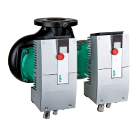
▪In the case of twin-head pumps, individually connect and secure
both motors.
▪Connect to 230 V low-voltage networks. When connecting to IT
networks (Isolé Terre electrical system), always make sure that the
voltage between the live wires (L1-L2, L2-L3, L3-L1 ➜ Fig.14C)
does not exceed 230 V. In case of error (ground fault), the voltage
between the live wire and PE must not exceed 230 V.
▪When switching the pump on or off using an external control
device, deactivate any mains voltage pulse (e.g. burst-fired con-
trol)!
▪Switching the pump via triacs/solid-state relays must be examined
on a case-by-case basis.
▪Make sure that the SELV lines have a maximum voltage of 24V!
▪During deactivation with on-site power relay: rated current ≥10A,
rated voltage 250VAC
▪Irrespective of the rated current of the pump, inrush peak currents
of up 10A may occur when the power supply is activated!
▪Observe the switching frequency:
– Switch-on/off procedures via mains voltage ≤100/24h
– Switch-on/off procedures via Ext. Off, 0–10V, or via bus com-
munication ≤20/h (≤480/24h)
▪It is advisable to protect the pump with a residual-current device
(type A or B in accordance with EN 60335).
▪Consider the leakage current per pump I
eff
≤ 3.5 mA.
▪The electrical connection must be made via a fixed connecting
cable equipped with a connector device or an all-pole switch with a
contact opening width of at least 3mm (VDE0700/Part1).
▪To protect against leakage and for strain relief to the threaded
cable connection use a connection pipe with sufficient outer dia-
meter ➜Fig.16. The cables near the screwed connection are to be
bent to form a drainage loop, to drain any accumulated drips.
▪Use a heat-resistant connecting cable where fluid temperatures
exceed 90°C.
▪Lay the connecting cable in such a way that it does not make con-
tact with the pipes or the pump.
Cable requirements
Terminals are intended for rigid and flexible conductors without
ferrules.
 Loading...

