1139300 Shadow 8 User Manual
A-2 Wiring Shadow 8 Heads Directly to WPC
Because WPC is rated NEMA 12 (protected against dust and oil), you must use conduit of
the same rating and make proper connections to ensure NEMA 12 protection.
4. Measure and cut Transmitter and Receiver wires so they reach the appropriate connectors
on the WPC 2000 Main Processor board or WPC 1000 Control board.
WPC 2000 wires must reach TB104 on a center- or right-mounted board; they must reach
TB101 on a left-mounted board. WPC 1000 wires must reach both TB101 and TB102.
5. Remove enough black PVC insulation so the conductors are exposed from the knockout to
the furthest terminal block they are required to reach.
First, make a shallow incision with an Exacto knife around the circumference of the cable,
then bend the insulation back and forth at the incision point and pull the insulation free.
6. Remove 3/16 to 1/4 in. of insulation from the end of each conductor, using a wire stripper.
7. Connect wires as shown in Table A-1 and in figures 11 (WPC 2000) and 12 (WPC 1000
New Style) at the end of the manual.
Connect the yellow Receiver wire to the yellow wire from the Program/Run/Start key
switch, using the crimp-type wire nut provided. Simply twist together the exposed ends of
both yellow wires, insert the wires in the wire nut, and secure the wires in the nut with a
crimping tool.
Make sure to terminate green (Earth) wires on both Receiver and Transmitter to a ground
stud inside the enclosure near the knockout through which you bring the wiring.
The pink Receiver wire and white and black Transmitter wires are not used. Cut these
conductors off near the enclosure entry and bind them to the other wires with a tyrap.
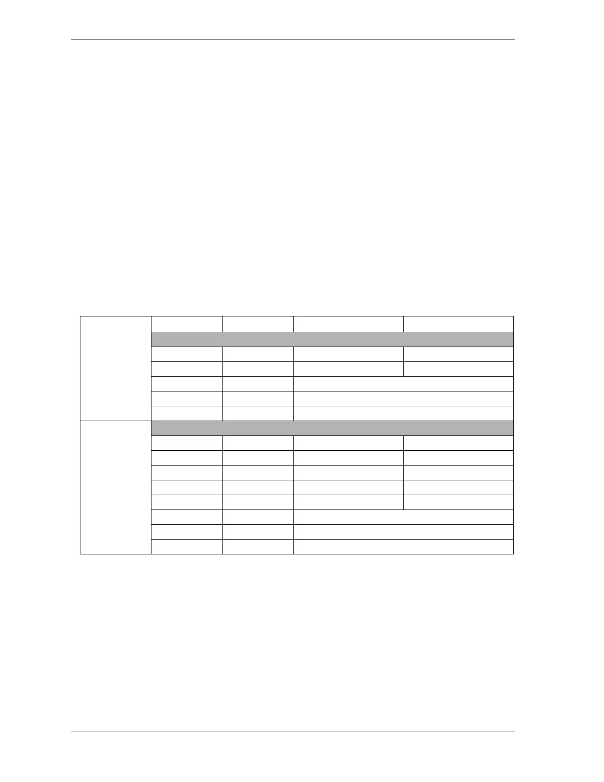
Table A-1. Shadow 8 Main Transmitter/Receiver Wiring Connections to WPC
Optic Head Wire Color Signal WPC 2000 Pin # WPC 1000 Pin #
Transmitter
Blue 0 Vdc 30 (TB103 Top) 28 (TB101 Bottom)
Brown 24 Vdc 42 (TB104 Top) 47 (TB102 Bottom)
White MTS Not used. Cut off unneeded wire.
Black MTS Ret Not used. Cut off unneeded wire.
Green Earth Terminate to ground stud near cable entry point
Receiver
Blue 0 Vdc 30 (TB103 Top) 28 (TB101 Bottom)
Brown 24 Vdc 42 (TB104 Top) 47 (TB102 Bottom)
Red EDM 30 (TB103 Top) 28 (TB101 Bottom)
Black OSSD 1 77 (TB103 Bottom) 8 (TB101 Top)
White OSSD 2 87 (TB104 Bottom) 21 (TB102 Top)
Yellow Start Connect to Start (Yellow) wire from key switch
Pink Aux Out Not used. Cut off unneeded wire.
Green Earth Terminate to ground stud near cable entry point


 To Next Page