Shadow 8 User Manual 1139300
Installation and Checkout 2-57
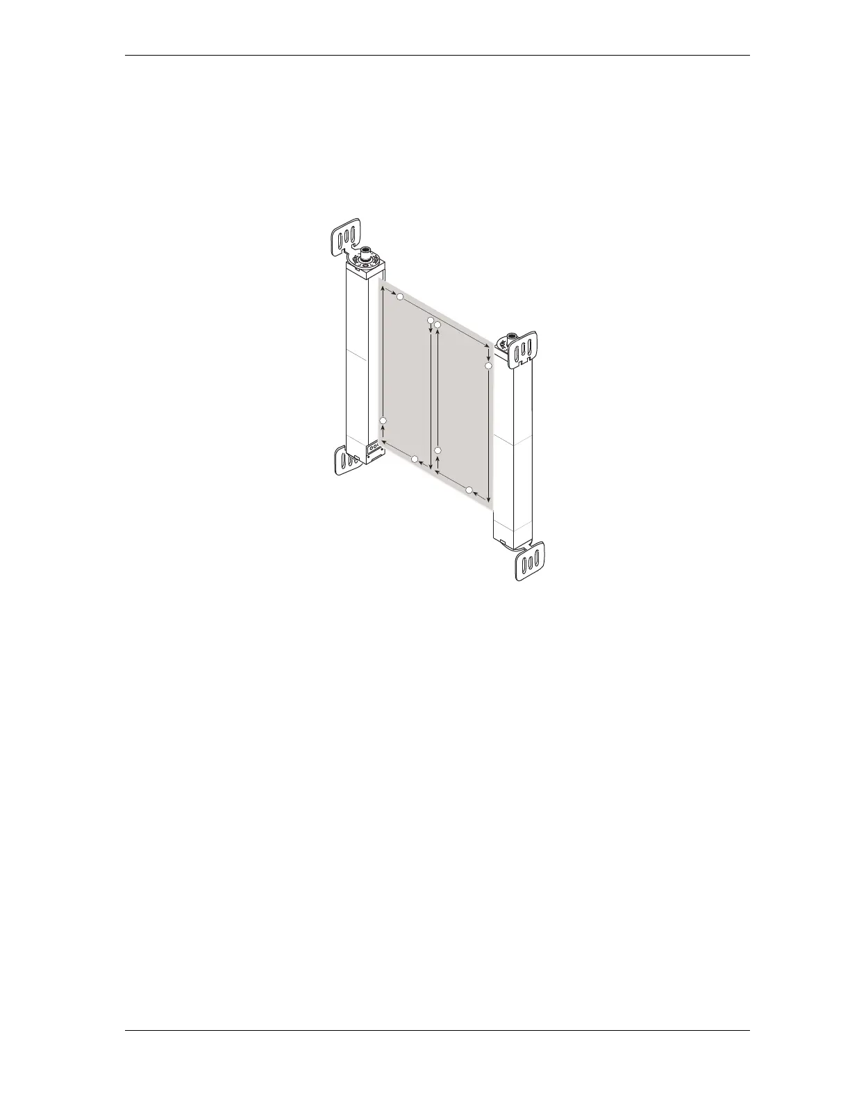
5. Interrupt the Shadow 8 sensing field with the shank of a 1/8-in. (3.2 mm) screwdriver to
check the unit’s alignment. Move the test object inside the perimeter (along the top, sides
and bottom) of the sensing field and up and down through the center of the sensing field,
as shown in Figure 2-26. The Machine Run/Stop LED on the Main Receiver should be
illuminated green.
If the Machine Run/Stop LED becomes illuminated red, the heads are misaligned. Align
the heads precisely, using the Individual Beam Indicators (IBIs) to help you, before
proceeding to step 6.
6. Interrupt the Shadow 8 sensing field with the 1.18-in. (30 mm) test object, using the
pattern described in step 5. Verify that the Machine Run/Stop LED is illuminated red
while the test object is anywhere in the sensing field. In addition, at least one Individual
Beam Indicator LED must be lit while the test object is anywhere in the sensing field.
If Shadow 8 is in Start/Restart Interlock mode, verify that the Machine Run/Stop LED is
illuminated red (Curtains Obstructed) and the yellow (Interlock/Alarm) LED is lit. Turn
the Program/Run/Start key switch to START before proceeding to step 7.
7. Enable the floating blanking option (see Setting a Floating Blanking Window, page 3-7),
and repeat step 6, using the 2.05-in. (52 mm) test object.
Figure 2-26. Test Object Pattern