1139300 Shadow 8 User Manual
2-32 Installation and Checkout
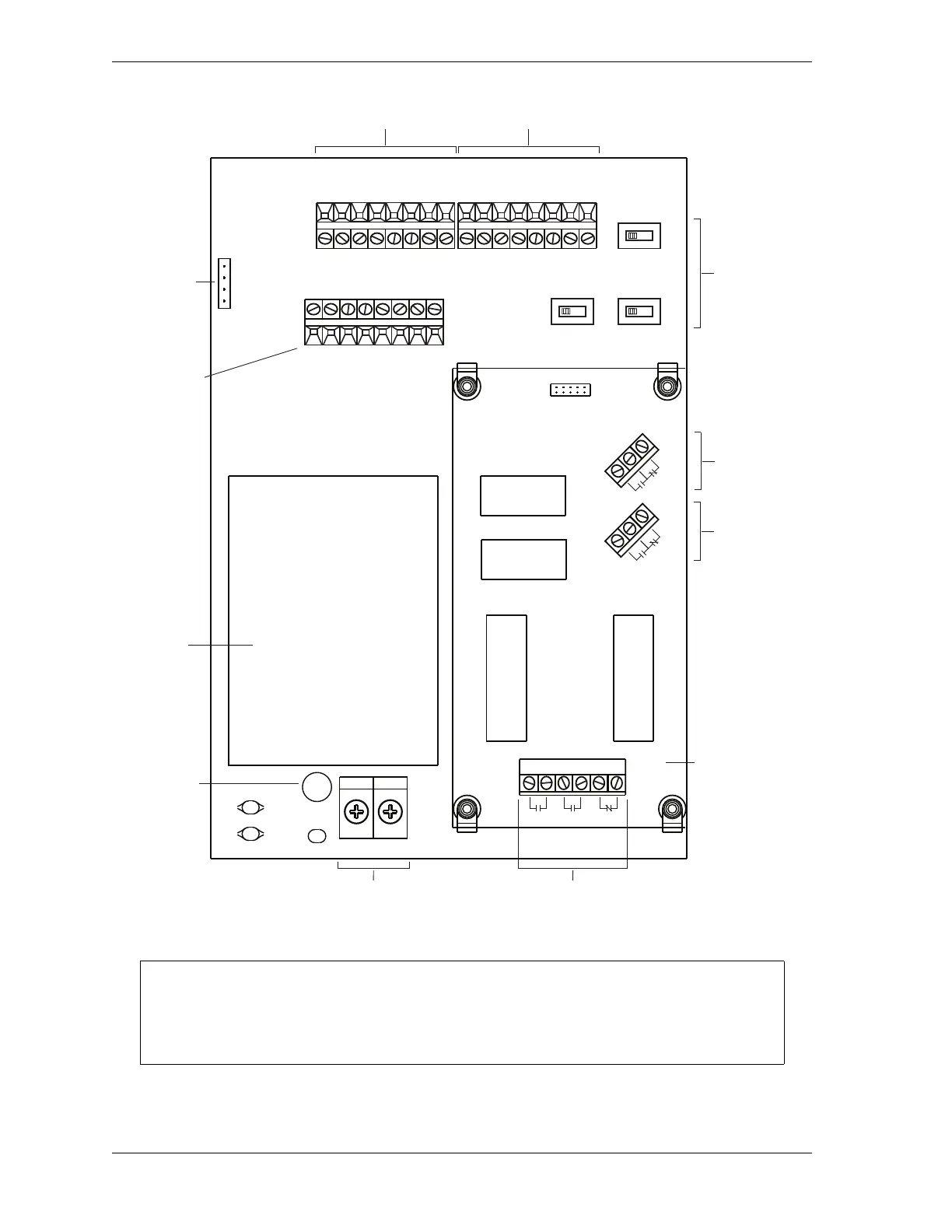
Figure 2-20. Shadow 8 Main Board: Location of Important Components
When joining cables with quick-disconnect fittings, be sure to make the connections
between the two cables as tight as you can make them by hand. Do not use tools such as
wrenches or pliers to tighten quick-disconnects.
Power
supply
AC power
connections
Stop relay output
connections
Auxiliary relay
output 1
connections
Relay board
Receiver connections Transmitter connections
C2
C1
RV1
TB2
J1
TB1
TB4
PS1
O.S.S.D.
(L) LINE (N) NEUT
K1
K2
+24 VDC
OSSD 2
MTS
CTL RET
Fuse
0 VDC
OSSD 1
AUX 1
EDM
START
SW2
AUX
PNP NPN
SW3
F3SJ
NO YES
SW1
EDM
INT EXT
1
109
2
N.O. 1 N.O. 2 N.C.
K3 K4
F1
COM +
TB20
+24 VDC
0 VDC
EDM
START
0 VDC
+24 VDC
CTL 1
CTL 2
CTL RET
MTS
J4
R1 R2 R3
TB5
TB6
AUX2
AUX1
N.O.
N.C.
N.O.
N.C.
COM -
AUX 2
CTL 1
CTL 2
TB3
Ribbon
cable
connector
Selector
switches
Connections
for EDM
Auxiliary relay
output 2
connections