1139300 Shadow 8 User Manual
2-26 Installation and Checkout
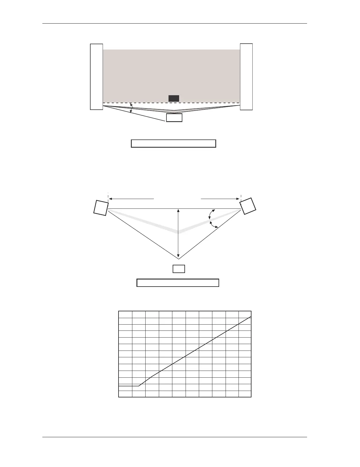
Figure 2-15 and Figure 2-16 show the minimum distance from the reflective surface, d, to one
side of the beam center line.
Figure 2-14. Unsafe Mounting, Example 2
Figure 2-15. Minimum Distance: Worst Case Alignment Example
Figure 2-16. Minimum Distance from a Reflective Surface as a Function of Range
Reflective Surface
Perimter of danger area
Reflection
Interruption
a
Sensing Field
Transmitter Receiver
Transmitter
Receiver
Beam Angle, a
d
Reflective Surface
Operating Range, R
a
a
Perimeter of danger area
0
100
300
500
700
900
2m
4m
6m
8m
10m
12m
14m
16m
Minimum distance
Range (m)
18m
20m
1.1m
1.3m
0.3m
d(mm)