Shadow 8 User Manual 1139300
Installation and Checkout 2-25
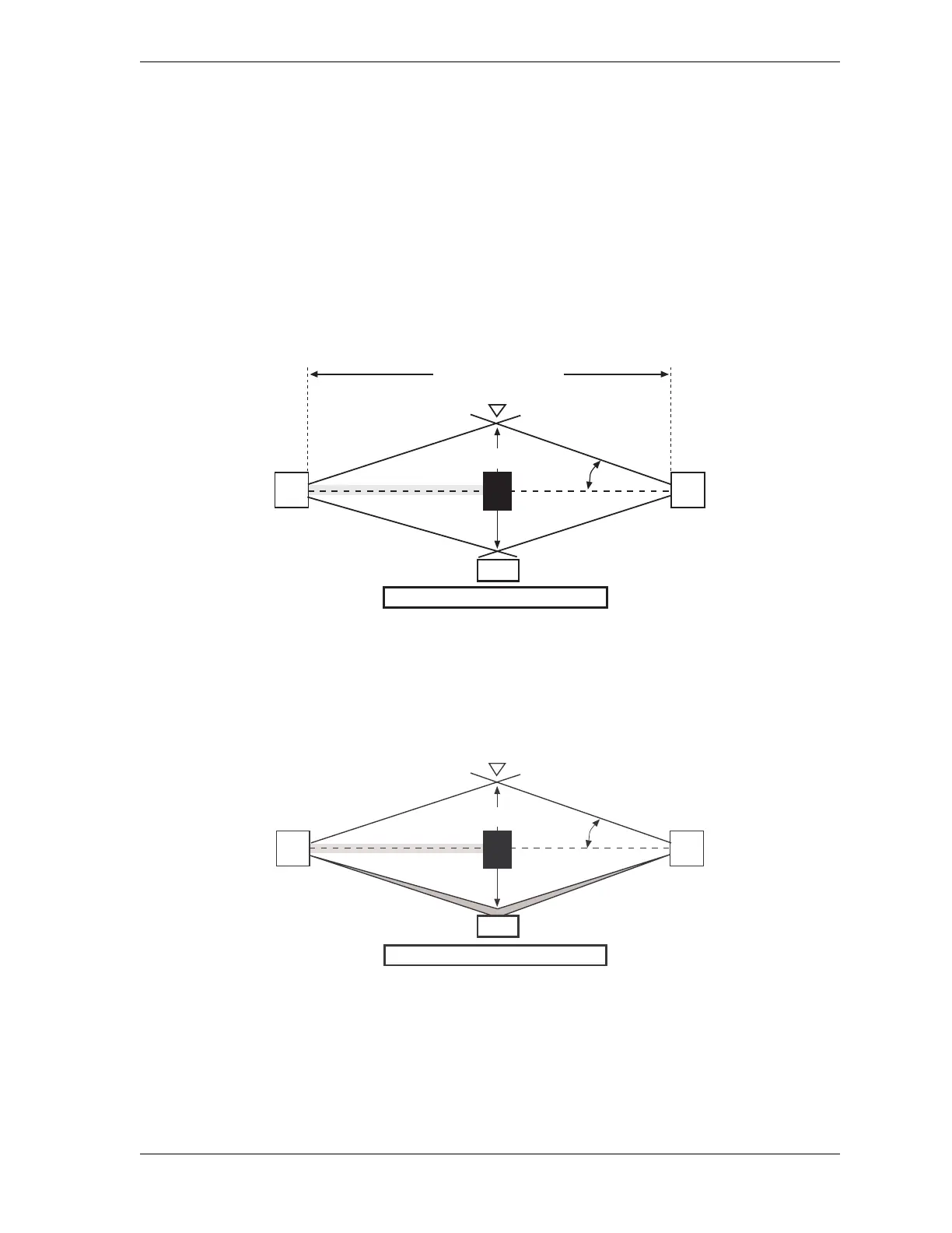
Reflective Surface Interference
A reflective surface adjacent to the sensing field can deflect the optical beam and may cause
an obstruction in the field not to be detected (see Figure 2-13, below, and Figure 2-14,
page 2-26). The reflective surface may be part of the machine, mechanical guard or
workpiece. Therefore, a minimum distance (d) must exist between the reflective object and
the center line of the Shadow 8 sensing field. The Test Procedure (see Test Procedure,
page 2-56) must be used to test for this condition.
In Figure 2-12, below, the interruption is clearly detected. The reflective object is outside of
the beam angle.
In Figure 2-13, below, the interruption is not detected because of the reflection. The reflective
object is inside the beam angle.
In Figure 2-14 (next page) the interruption is not detected because of the reflection.
Reflective surface interference may also appear above and below the sensing field.
Figure 2-12. Correct Mounting Example with Proper Alignment
Figure 2-13. Unsafe Mounting, Example 1
Transmitter
Receiver
Approach direction
Central beam
Light beam interrupted
d
Reflective Surface
Perimeter of danger area
Interruption
a
Beam Angle, a
Operating Range, R
Transmitter
Receiver
Approach direction
Central beam
Light beam interrupted
d
Reflective Surface
Perimeter of danger area
Reflection
Interruption
a
Beam Angle, a