1139300 Shadow 8 User Manual
2-34 Installation and Checkout
11. Insert the gland nut coupling through the top center knockout of the control box.
12. From inside the control, thread the 1 1/16 in. locknut through the bundle of connectors
until it contacts the coupling, then tighten the nut onto the threads with your hands.
13. Tighten the nut securely with a 1 1/16 in. (27 mm) wrench.
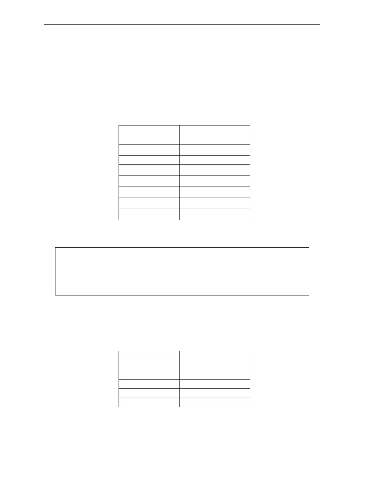
14. Connect receiver wires to terminal block TB2 on the Shadow 8 Main board, as shown in
Table 2-5, below, and Figure 1 at the end of the manual.
* Terminate green wire to ground stud inside enclosure
near cable entry point.
15. Repeat steps 6-13 for the transmitter cable.
16. Connect transmitter wires to terminal block TB20 on the Shadow 8 Main board, as shown
in Table 2-6 and Figure 1 at the end of the manual.
* Terminate green wire to ground stud inside enclosure
near cable entry point.
Table 2-5. Main Receiver Wiring Connections
Wire Color Signal Label (TB2)
Brown +24 Vdc
Blue 0 Vdc
Black OSSD 1
White OSSD 2
Pink Aux 1
Red EDM
Yellow Start
Green Ground stud *
To connect a wire, find the correct terminal and loosen the screw over it by turning it
counterclockwise. Insert bare wire into the terminal 90% of the way. Tighten the screw. The
metal tooth inside the terminal will clamp down on the bare wire for a tight connection. Make
sure that the metal tooth is clamped down on the bare part of the wire, not on the insulation.
Table 2-6. Main Transmitter Wiring Connections
Wire Color Signal Label (TB20)
Black Ctl Ret
White MTS/Test
Blue 0 Vdc
Brown +24 Vdc
Green Ground stud *