Chapter 2: Getting Started
EN-26
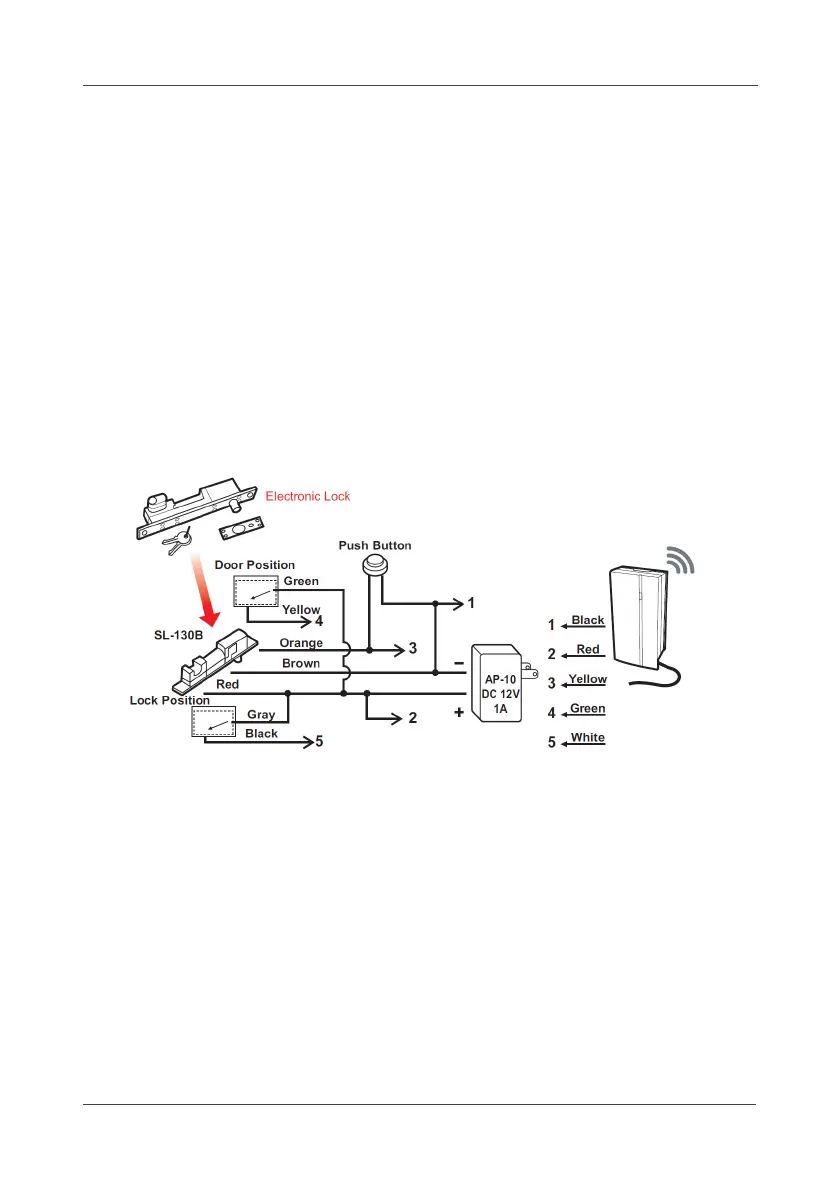
2.4.11 Lock Switch(LA5580)
a. Power on the device.
b. Connect the wiring pin of 3rd party lock.
c. The Pin functions are as below:
Wire 1- (Red) DC +12V Power Input
Wire 2- (Black) Common
Wire 3- (Yellow) Open Collect Digital Output (12V / 120mA Max.)
Wire 4- (Green) Open/Close status 0V, 12V DC Level input (active high)
Wire 5- (White) Lock/Unlock status 0V, 12V DC Level input (active high)
d. To connect the SL-130B Electronic lock as example, please see the
following diagram:
e. Mount the bracket on the wall.