Lubricator Operating manual
Revision: 02
2022-D064493
en-24
7.1.2 Standby – Time control
The 24 V version can be switched off completely by switching off the supply voltage. The presettings
are not getting lost.
The battery version can be put into standby via a potential-free limit switch between PIN 2 and PIN 3.
Maximum cable length is 5m.
8 Pulse control
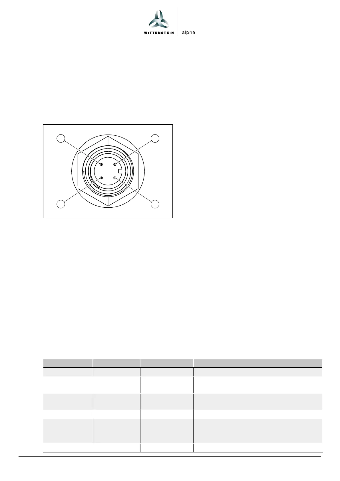
M12x1 connector for external controller
1
2
4
3
1. PIN 1,
+
24 V DC
2. PIN 2, control signals
3. PIN 3, ground
4. PIN 4, output signals
The lubricator has a 4-pin plug connector for connection to the controller of a machine (for external
control of the lubricator). This is located at the bottom of the housing.
8.1 Control signals (PIN 2)
This section describes the signals for controlling the lubricator from an external controller. The values
and settings refer to the factory settings of the lubricator, see section “6.1 Adjustable parameters”.
The lubricator is controlled exclusively by means of high-level signals on PIN 2.
8.1.1 Overview of control signals
The lubricator provides the following predefined control signals (input signals).
Signal length Designation Function Description
2sec high 2sec signal 1 pump stroke Execution of a single lubricating sequence
3sec high 3sec signal 2 pump strokes Execution of two successive lubricating se-
quences
4sec high 4sec signal C pump strokes Lubricating sequences according to the set-
ting of parameter C
6sec high 5sec signal 40 pump strokes Venting or filling function
10sec high 10sec signal Error
acknowledge-
ment
Acknowledgement of error messages
12sec high 12sec signal 40 pump strokes Venting or filling function