8. Slide the tines of the Head Assembly Power Cable Strain Relief around the base
sides of the Head Power Plug connection.
9. Line up the holes of the Head Assembly Power Cable Strain Relief to the holes on
the head grabber arm.
10. Holding the head in position so that the head
lines up neatly to the Head Assembly Power Cable Strain Relief on
the head grabber arm, screw in the two 5/8” screws, making sure they
go into the Head Assembly Power Cable Strain Relief and the head
grabber arm and then into the head. Tighten rmly.
11. Replace the gantry cover and attach using the two screws that were
removed earlier.
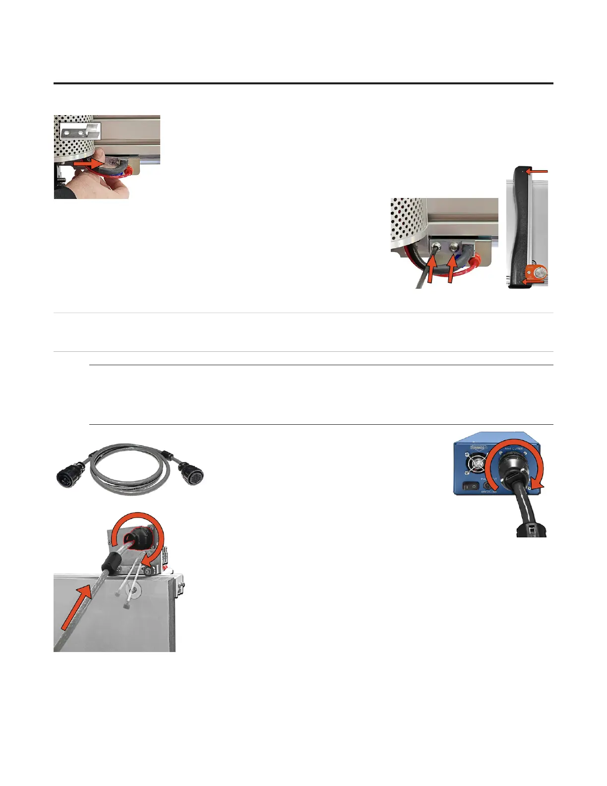
Hooking up the Gantry and Air Lines
Connecting the Board Cable
*Carefully align the pins of the board cable before applying
pressure to plug it in. The connector is keyed to avoid incorrect
pin alignment. Forcing the connector will result in damage.*
1. The board cable connects the gantry on the
CMC to the ECU. Connect the male end of the
board cable to the back of the ECU by aligning the
pins and turning the locking ring until it seats itself
and locks into place.
2. Connect the female end of the board cable to the back of the gantry in the
same manner.
3. Move the gantry to the far right of the CMC and back to the left to make sure
the board cable does not get caught on anything. If the board cable is obstructed,
this will aect the cuts.
10
Wizard™ International, Inc., 4600 116th St. SW, Mukilteo, WA 98275 888/855-3335 wizardcutters.com
20-34300-1A GettingStartedManual9K-70FrameShop
02/23/24
Wizard™ CMC Model 9000 Hardware and Software Getting Started Guide