Check Squareness
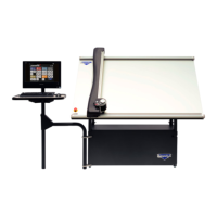
Check the Drive Belt Lines
Move the gantry all the way to the left. Move the gantry slowly
toward the right until a red mark is visible on the drive belt of the
upper gantry. Conrm that the red mark lines up with the red mark
on the toothed pulley.
Without moving the gantry,
look at the lower drive belt
of the gantry and make sure
the red mark lines up on
the lower drive belt and the
toothed pulley. If they do
not, call Wizard Technical
Support.
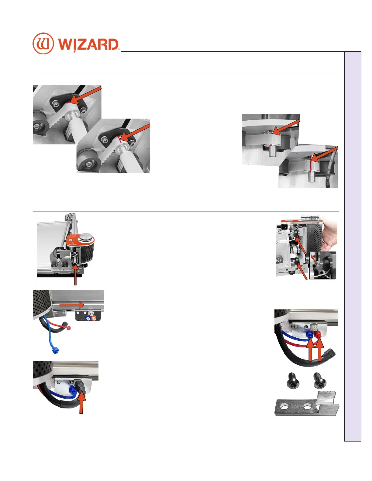
Head Installation
Install the Head onto the Gantry
1. Move the gantry to the right edge of the CMC.
2. Point the head so that the footblock faces toward the CMC
and the wheels are close to the bottom of the gantry.
3. Line up the wheels on the head to the center channels of
the gantry arm and ease the head onto the gantry.
4. Roll the head up the gantry until it lines up to the head grabber arm on the right
side of the gantry.
5. Connect the air to the head by twisting the two air ttings
together, matching colors.
6. Connect the head power plug (square connection) to the
head grabber arm.
7. Locate the Head Assembly Power Cable Strain Relief and
the two 5/8” screws.
20-34300-1A GettingStartedManual9K-70FrameShop
02/23/24
9
Wizard CMC Model 9000 Hardware and Software Getting Started Manual
Wizard™ CMC Model 9000 Hardware and Software Getting Started Guide