44
3062878_201707
Parameter Setting range Factory setting
Diff. pressure sensors, number 1 - 2 2
Supply air 0-6000 Pa 0-1000 Pa
Extract air 0-6000 Pa 0-1000 Pa
Diff. extract fan -50 - 50 % 0 %
Number of supply air fans 1-10 1
Supply fan k factor 0 - 2000 0
Fan type 1 - 2 1
Number of extract air fans 1-10 1
Extract fan k factor 0 - 2000 0
Fan type 1 - 2 1
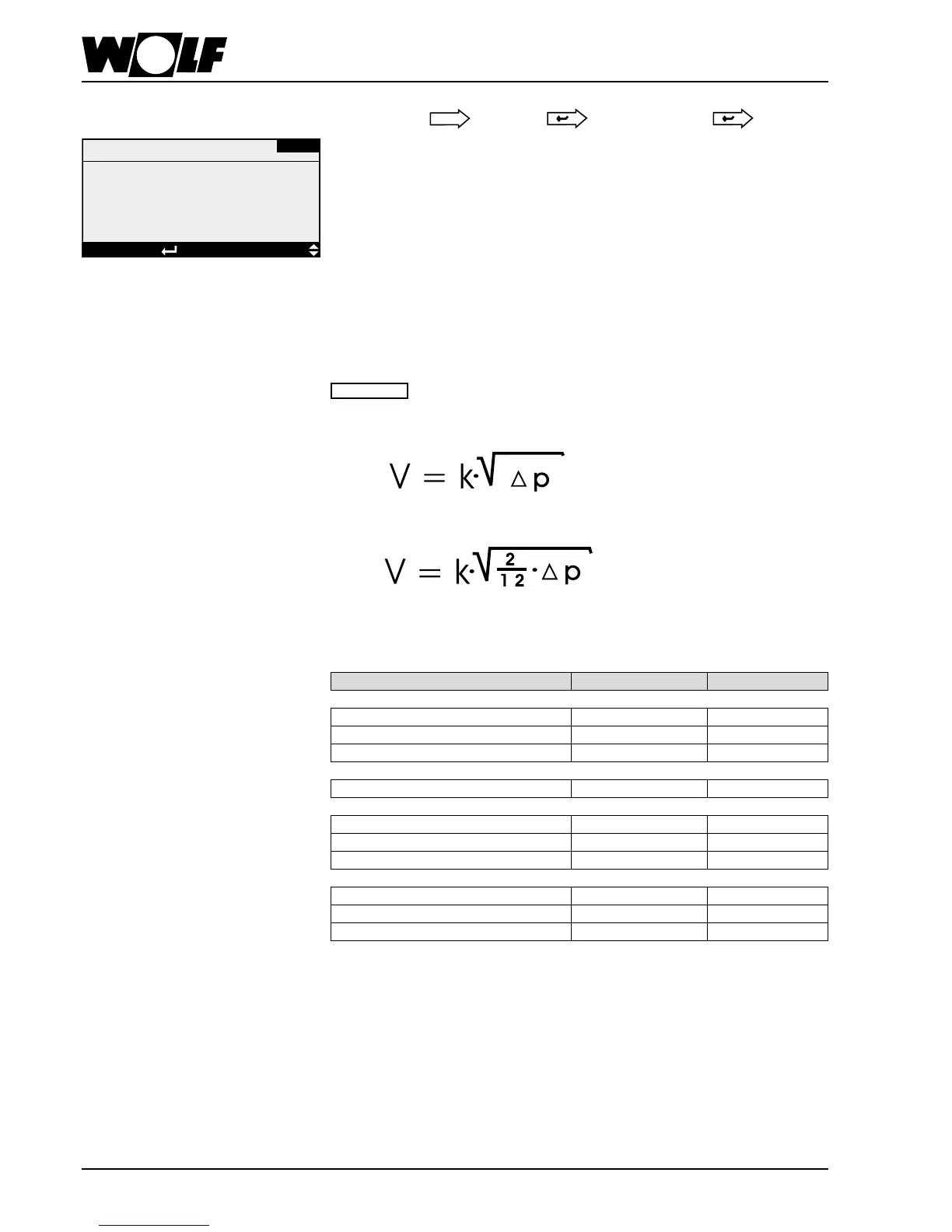
Standard mask
Main menu Heating contractor Press/
owratectl
The number of pressure transducers and the measuring range can be defaulted via a
parameter.
The number of pressure transducers and the measuring range can be defaulted via a
parameter.
In ventilation systems with a pressure transducer, the supply air pressure is captured
and compared with the selected set value. The supply air fan is then switched in
line with the deviation. The extract air fan is switched according to the switching of
the supply air fan (in %) + "Diff. extract fan". By entering the k factor, the captured
pressurewillbeconvertedintoowrate.
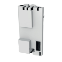
For this, the respective fan type must be selected for every fan.
Furthermore, a number for supply/or extract air fans is adjustable. The measured
volumeowforsupplyorextractairismultipliedaccordinglybythissetting.The
prerequisite for correct calculation is that the design of the supply or extract air fans is
identical and that they are actuated parallel to one another.
10.2.15Pressure/owrate
Press/owratectl
DISPLAYSELECTIONEsc BACK
Diff. pressure sensors
Number -2-
Type 0/10 V, supply air:
0/1000.0 Pa
Extract air: 0/1000.0 Pa
DV-01
10. Operating level 2
The k factor is stated on the fan type plate.
Fan type 1 corresponds to the formula
Fan type 2 corresponds to the formula
Theformulaeforcalculatingtheowratecanalsobefoundonthefantypeplate.