76 3064298_201507
Systemconguration51
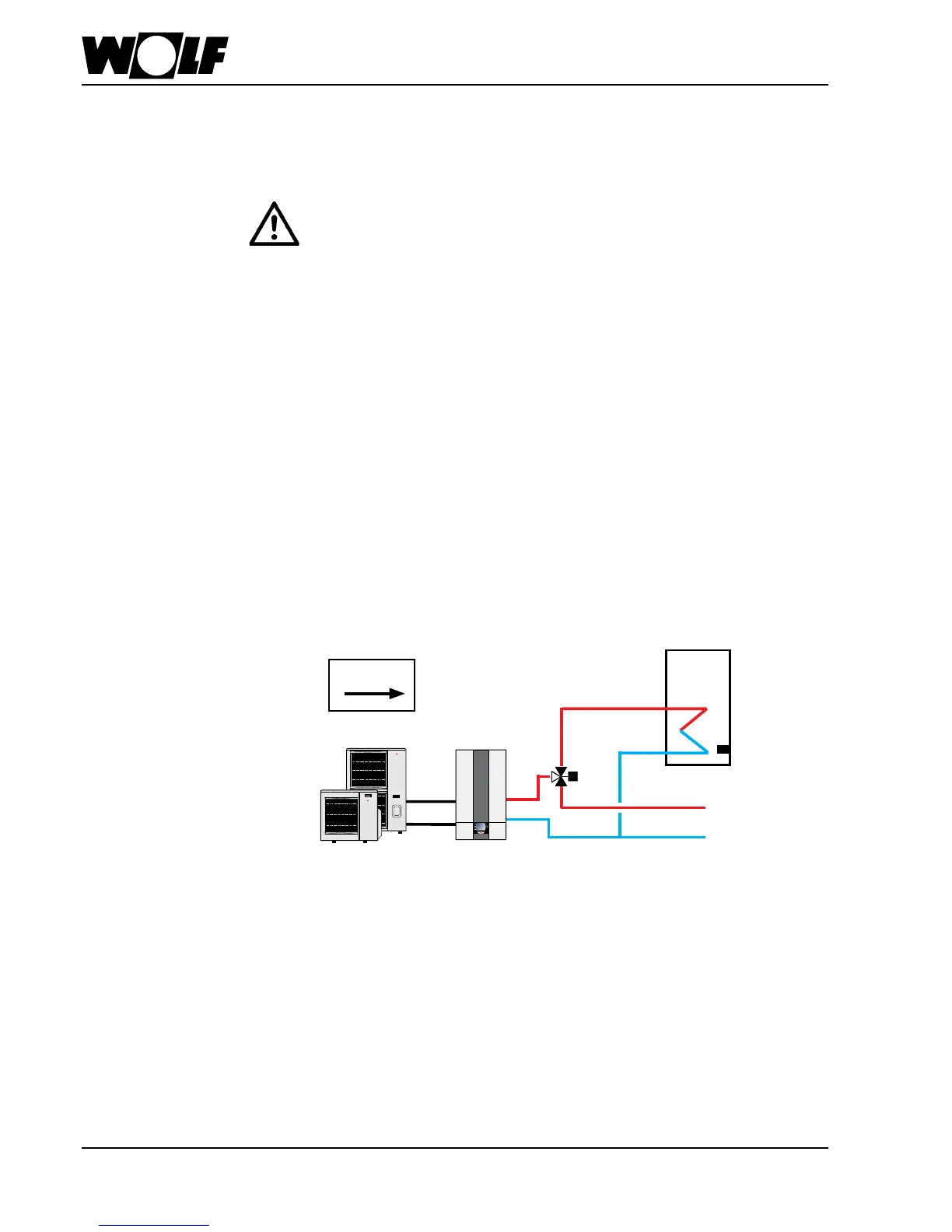
BWL-1S(B)
● Split air/water heat pump
● 0 - 10 V switching (at input E2)
●Active cooling possible
0 - 10 V
3WDV
HTG/DHW
CTS
A
B
AB
Important information:
In these schematic diagrams, shut-off valves, air vent valves and safety equipment are not fully represented.
These should be provided for each individual system, in line with the applicable standards and regulations.
Hydraulic and electrical data can be found in the Hydraulic System Solutions technical guide.
U = 0…10 V at input E2/SAF:
0V ≤ U < 1.2V → heatpumpOFF
1.2V ≤ U ≤ 4.0V → 0-100%compressorcoolingmode
4.2V ≤ U ≤ 7.0V → 0-100%compressorheatingmode
7.2V ≤ U ≤ 10.0V → 0-100%electricheatingheatingmode
Notes:
- Connect the outside temperature sensor OTS
- Activate the electric heating (WP090)
- Program WP003 for defrost
→indefrostmode,outputA1isswitchedinordertonotifytheBMSregarding
defrost mode.
External demand / control by
building management system BMS
DHW heating mode for system
conguration51
DHWmodecanbesuppressedforsystemconguration51byremovingthecylinder
sensorCTS,carryingoutaparameterresetandresettingthesystemconguration.
A 3-way diverter valve for
central heating/DHW and a
feed/heating circuit pump
are integrated into the
indoor module
Indoor moduleOutdoor module
Integrated 3-way diverter valve
for heating/DHW must be
disconnected.