37 | Page
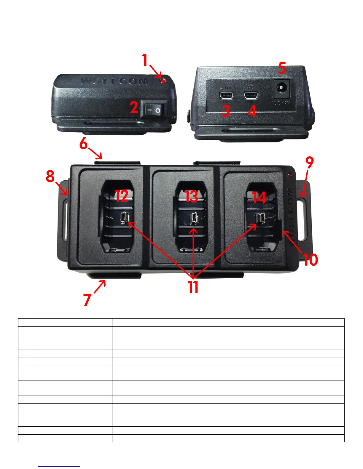
Wolfcom Vision Docking Station Layout
If the Docking station is powered on the LED will turn "RED"
Used to power on and off the docking station.
This USB connection is used when multiple docking stations are used and
linked together. USE Cable #7 Only.
This USB connection is for connecting to a computer. USE Cable #2&3 Only.
Used for Supplying power to multiple units. USE Cable 5&6 Only.
Used for locking connected additional docking stations. (Recommend side for
linking)
Used for locking connected additional docking stations.
Used for secure mounting options in a vehicle, on a wall or table.
Used for secure mounting options in a vehicle, on a wall or table.
For use in "Car Mode". If the Wolfcom Vision REC light is set "ON" or
"FLASH" you will see the REC light indicator while it is recording.
3 Mini USB connectors for the Wolfcom Vision and accessories
Used to charge, transfer and or link the Vision and Accessory Packs
Used to charge, transfer and or link the Vision and Accessory Packs
 Loading...