Pre-Installation
Greenstar 8000 Life – 6720883866 (2019/04)
10
[13] Ignition electrodes
[14] Flame sensing electrode
[15] Flow temperature sensor at flow pipe
[16] Heating block temperature limiter
[17] Flow temperature sensor at heating block
[18] Inspection cover
[19] Condensate sump
[20] Gas valve
[21] Drain point
[22] Control unit
3.9 Product data for energy consumption
The product data on energy consumption can be found in the operating
instructions for the user.
4 Pre-Installation
NOTICE:
Risk of damage to system or appliance!
Before installation
▶ All the following Pre-Installation sections must be read and
requirements met before starting appliance or flue installations.
4.1 System preparation
4.1.1 Artificially softened water
It is possible to have an ion exchange water softener fitted to the cold
water system of the property. However, the appliance requires an
untreated cold water connection taken from the mains supply, before the
water softener, to the primary water filling point of the heating system.
Alternatively there are water softening/treatment appliances that do not
adjust or alter the pH levels of the water. With these appliances it may not
be necessary to provide an untreated water by-pass to the primary water
filling point of the heat system.
NOTICE:
▶ Salt based softened water must not be used to fill the central heating
system.
4.1.2 Water systems and pipe work
Primary system plastic pipework:
• Any plastic pipe work must have a polymeric barrier, complying with
BS 7921 and installed to BS 5955 with 600mm (minimum) length of
copper connected to the appliance.
• Plastic pipe work used for under-floor heating must be correctly
controlled with a thermostatic blending valve limiting the
temperature of the circuits to approximately 50°C with 1000mm
(minimum) length of copper or steel pipe connected to the
appliance.
Primary system/connections/valves:
• Do not use galvanised pipes or radiators.
• All system connections, taps and mixing valves must be capable of
sustaining a pressure of 3 bar.
• Radiator valves should conform to BS 2767:10.
• All other valves should conform to BS 1010.
• It is best practice to fit Thermostatic Radiator Valves (TRV's) to all
radiators, except the area where the room thermostat is sited which
must be fitted with lockshield valves that are left open.
• If the circulating pump speed is fixed and system circulation can be
significantly adjusted or stopped by TRV's or zone valves, a system
bypass should be installed to give at least a 3 metre circuit when
activated. However; any appliance fitted with a modulating pump
may not require a system bypass.
• Drain cocks are required at all the lowest points on the system.
• Air vents are required at all high points on the system.
Primary system considerations - Regular appliances
Open vent
• Close Coupled feed and expansion arrangement:
– The open vent pipe and feed and expansion pipe must rise
continuously from the appliance and be a maximum of 150mm
apart.
– The feed and expansion cistern must be positioned to provide a
minimum static head of 250mmabove the highest point in the
heating system to the water level in the feed and expansion
cistern.
– Ensure adequate space is left in the expansion cistern for
expansion of the system water.
• No valve shall be fitted in the open vent pipe or the feed and
expansion pipe.
• The open vent pipe must be at least 22mmØ.
• The feed and expansion pipe must be at least 15mmØ.
Sealed system (appliance converted to operate on a sealed system)
• The CH sealed system must be filled using a WRAS approved filling
loop or comply with examples in 4.1.4 "System fill" section.
• An expansion vessel, of a size suitable for the system, must be fitted
as close as possible to the appliance in the central heating return.
• Also fit a pressure gauge, a 3 bar pressure relief valve and stop cock
(fixed cylinder type or sealed system approved connection).
• No valve shall be fitted that can isolate the appliance from the
expansion vessel or pressure relief valve.
• An automatic air vent must be fitted.
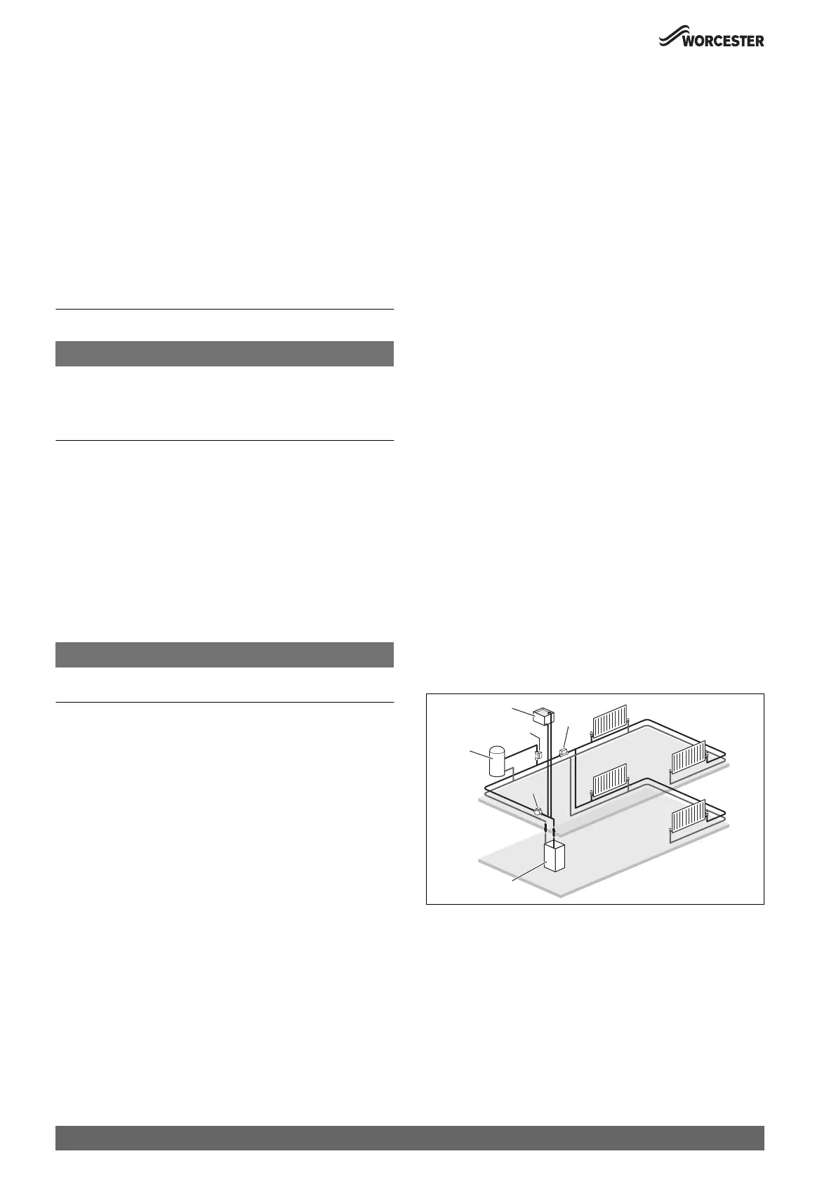
4.1.3 System layouts examples
Open vent primary system - Cylinder and central heating zone:
Typical S-Plan example
• The cylinder return must be the last connection on the common
return pipe to prevent reverse circulation.
Fig. 4 Cylinder and heating zone
[1] Appliance
[2] Zone valves
[3] Domestic hot water cylinder
[4] Circulation pump
[5] Feed and expansion tank
1
4
2
2
3
5
0010021234-001

 Loading...