Commissioning
37
Greenstar 8000 Life – 6720883866 (2019/04)
5.5.2 Cable preparations
NOTICE:
Damage to control unit!
Small pieces of wire can cause shorts and damage to electronics.
▶ When stripping wires always ensure copper strands do not fall into
the control box.
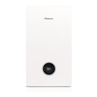
Mains voltage (power cables), example figure 55
▶ Ensure the conductors (C) can reach the appropriate terminal
connection and that the protective (earth) conductor is longer than
the other wires.
– Power cables connected to the appliance my have different
conductor lengths depending on the termination point.
Fig. 55 Mains voltage (power cables) preparation
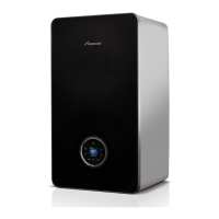
Low voltage (signal cables), example figure 56
Fig. 56 Low voltage (signal cables) preparation
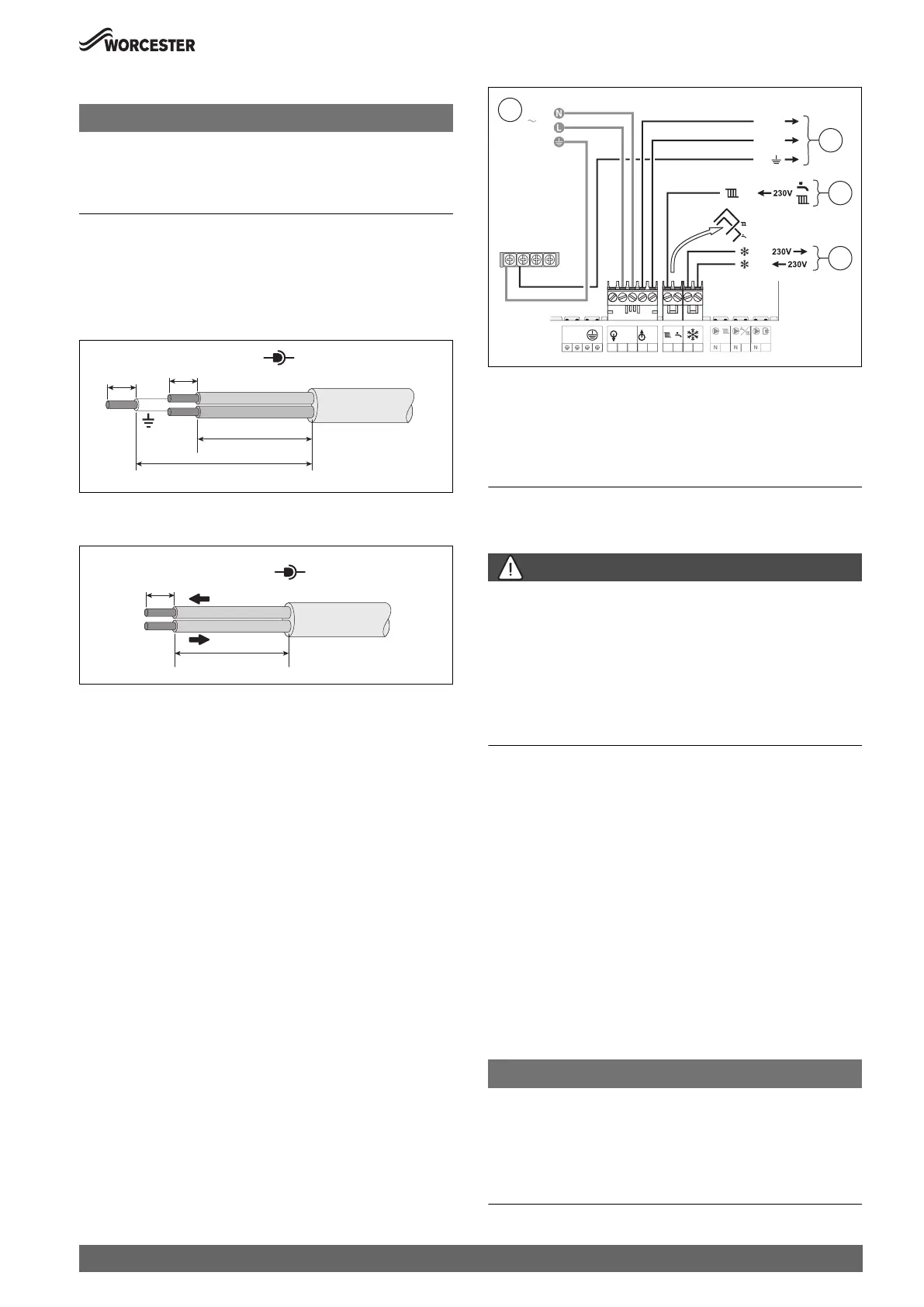
5.5.3 External controls - domestic installations
Appliance external control connections example
▶ The electrical power supply to the external equipment [2] is supplied
from 230V OUT - L (Live), N (Neutral) and \ (earth) terminals.
▶ The Switch Live from the external equipment [3]:
– Both pre-wired links are removed, the CH demands are combined
and wired to the (LR terminal.
▶ External frost thermostat connections [4]:
– The Live supply is terminal FS
– The Switch Live is terminal FR
Fig. 57 External controls connections example
[1] 230V mains supply to the appliance.
[2] 230V supply from the appliance to the wiring centre.
[3] CH Switch Live (Demand) from the external controls.
[4] External frost protection Live supply and Switch Live (Demand).
6 Commissioning
6.1 Pre-Commissioning checks
DANGER:
Risk of electric shock!
▶ Isolate electrical components from the power supply (230 V AC)
(fuse, circuit breaker) and secure against unintentional re-
connection before carrying out any work.
Information on safe isolation can be found in the Health and Safety
Executive guidance HSG85.
▶ Check for zero potential before proceeding with work, using test
equipment approved to GS38 to confirm that the electricity supply is
disconnected.
Checks before commissioning:
▶ Check that the service and water pipes are connected correctly.
▶ Check the gas type specified on the identification plate matches that
of the gas supply and that the gas supply is properly purged.
▶ Appliance converted to sealed system.
– Check that the appliance is filled with water and under pressure
(1.5 bar) and that there are no leaks.
▶ Check that the electrical connections of the appliance are correct:
– Mains electrical supply - 230V, 50Hz
– Compliant earth connection
– Correct polarities.
– External equipment and controls are wired in correctly.
▶ Check that the flue is correctly fitted, airtight, free from any
obstruction and the connections are secure.
▶ Check that the condensate pipe work is connected properly and that
there are no leaks.
NOTICE:
If the appliance is not to be commissioned immediately then, after
successfully completing all of the checks and any rectification work:
▶ Isolate the electricity supply.
▶ Isolate the gas supply.
▶ Drain the system and appliance.
▶ Label appropriately.
0010023711-001
> C
C
6-8mm
6-8mm
N
L
230V
0010012956-001
26-30mm
6-8mm
0-30V
1
0010022788-001
FS
FR
PE
P
PW
FS
FR
LR
LR
PW
N
IN
230V
OUT
230V
LN
L
230V AC
LR
3
L
N
2
4
230V OUT

 Loading...