Pre-Installation
Greenstar 8000 Life – 6720883866 (2019/04)
18
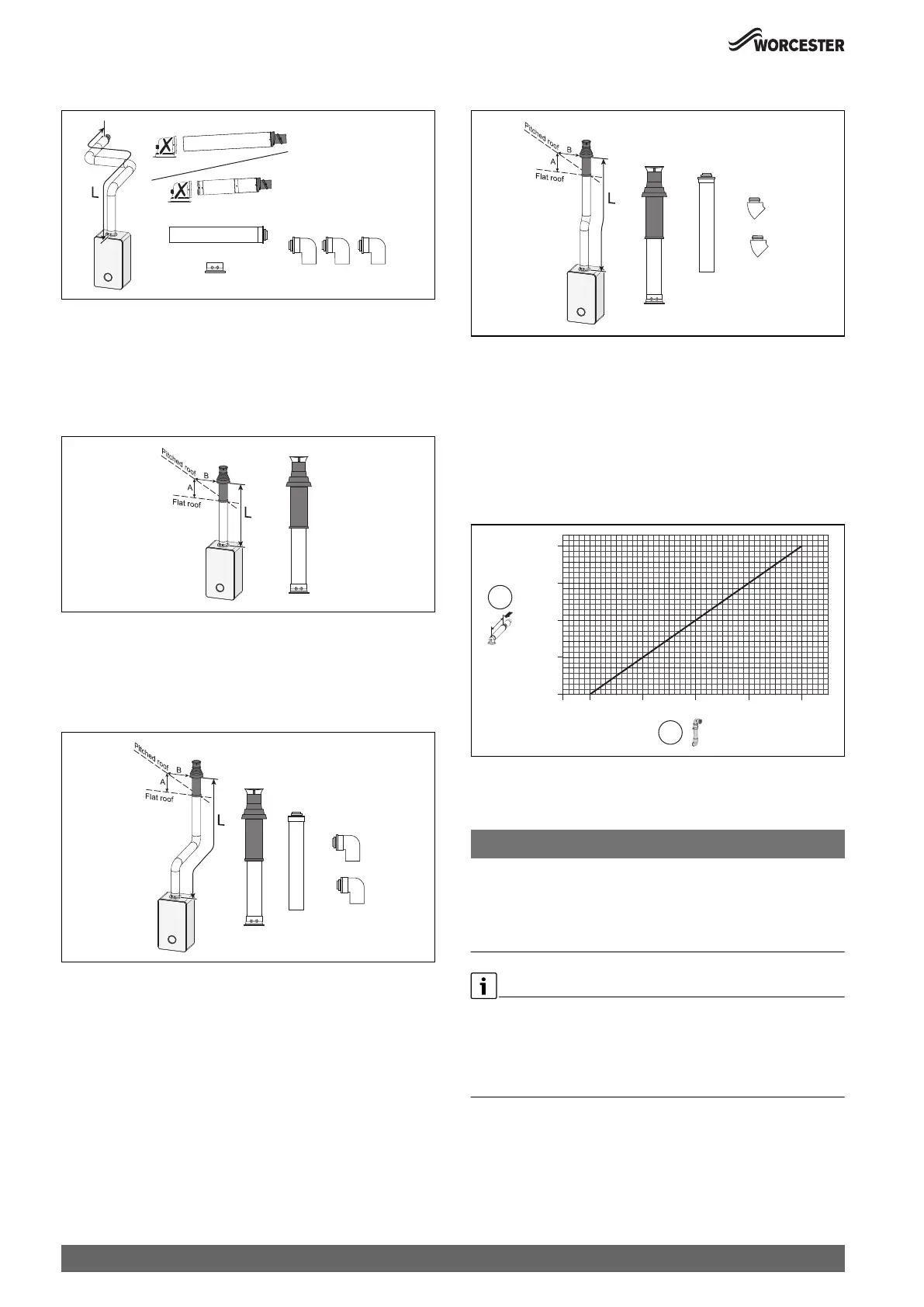
High level horizontal flue with additional 90° elbows
Fig. 23 Horizontal flue option
• Flue length [L] (initial bend included in length calculation)
– Maximum flue length as stated in Table 9 "Maximum flue lengths
- Horizontal flues" minus 2 x 90° bends equivalent straight flue
length as stated in Table 11 "Effective length of bends".
Vertical balanced flue assembly
Fig. 24 Vertical flue option
• Flue length [L]
– Maximum flue length as stated in Table 10 "Maximum flue
lengths - Vertical flues".
Vertical balanced flue with 90° elbow offset
Fig. 25 Vertical flue option
• Flue length [L]
– Maximum flue length as stated in Table 10 "Maximum flue
lengths - Vertical flues" minus 2 x 90° bends equivalent straight
flue length as stated in Table 11 "Effective length of bends".
Vertical balanced flue with 45° elbow offset
Fig. 26 Vertical flue option
• Flue length [L]
– Maximum flue length as stated in Table 10 "Maximum flue
lengths - Vertical flues" minus 2 x 45° bends equivalent straight
flue length as stated in Table 11 "Effective length of bends".
4.4.3 Plume management system
For every extra 1,000mm of plume management after the first 500mm,
the internal 60/100 flue length must be reduced by 700mm, up to a
maximum of 4,500mm of plume management.
Fig. 27 Reduction to flue length as plume length increases graph
[1] Reduction to flue length [mm] (maximum reduction 2,800mm)
[2] Plume length [mm] (maximum plume length 4,500mm)
NOTICE:
Plume management length:
▶ The plume management length must be a minimum of 500mm and
must not exceed the maximum straight length for a horizontal Ø 60/
100mm flue with a 60mm plume management system as stated
previously.
Horizontal plume management runs
▶ The initial horizontal run from the terminal elbow must have a
minimum 10° fall back, (stop tabs in the elbow prevent less than 10°)
to the appliance for proper disposal of condensate.
▶ Any further horizontal runs after an elbow can be 3°.
0010015198-001
0010015199-001
= 300 mm
B = 500 mm
0010015200-001
= 300 mm
B = 500 mm
0010015201-001
= 300 mm
B = 500 mm
0010023114-001
0
700
1,400
2,100
2,800
500 1,500 2,500 3,500 4,500
[mm]
[mm]
2
1

 Loading...