Commissioning
41
Greenstar 8000 Life – 6720883866 (2019/04)
NOTICE:
Do not continue commissioning until the correct gas pressure is
achieved.
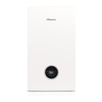
Gas supply pressure drop
Fig. 62 Natural Gas pressures
[≤ ] Less than or equal to
[>] Greater than
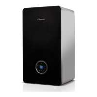
Fig. 63 L.P.G. pressures
[≤ ] Less than or equal to
[>] Greater than
6.7 Checking the gas rate
▶ The gas rate should be measured at the gas meter after the appliance
has been operating for a minimum of 10 minutes at maximum output.
▶ Refer to Technical data section of this manual for the appliance gas
rates and CO/CO
2
ratios.
▶ Where a gas meter is not available (e.g. L.P.G.) the CO/CO
2
must be
checked.
▶ Gas rate must be checked with the appliance in service, maximum
output test mode.
▶ Carry out Gas rating procedures as described in current edition of the
“Essential Gas Safety”.
▶ Ensure all other gas appliances are isolated when carrying out the gas
rate check on the appliance.
▶ Set the chimney sweep mode and start up the appliance at maximum
rated output.
▶ Where a gas meter is not available (e.g. L.P.G.) the CO/CO
2
must be
checked to the units shown in the setting of the air/gas ratio.
▶ If pressure and gas rate are satisfactory press the OK key or the d
key and the boiler will return to normal operation.
6.8 Checking for gas leaks during operation
▶ Use an approved gas leak detector to check all connections for
possible leaks. The product must be certified as a gas leak testing
agent.
▶ Do not allow the product to come into contact with the electrical
wiring.
6.9 CO and combustion check
The following combustion and flue integrity checks are mandatory and
these values must be recorded on the Benchmark check list, at the end
of these instructions.
Once the gas rate and pressure have been confirmed as acceptable then
the CO and combustion checks can be undertaken.
The flow chart is given for guidance, the details of the checks are given in
the following sections:
• Checking flue integrity, ( chapter 6.10)
• Flue gas analysis, ( chapter 6.11)
NOTICE:
Before CO and combustion checks:
▶ Verify the appliance is connected to the correct gas type.
▶ Ensure the appliance is supplied with the correct gas inlet pressure
and gas rate as specified previously in the Commissioning section.
▶ Visually check the integrity of the whole flue system and confirm that
all the components are correctly assembled, fixed and supported.
▶ The flue gas analyser must be the correct type as specified in BS
7967. Before use the analyser must have been calibrated as
specified by the manufacturer. The installer must be competent in the
use of the analyser.
▶ Check and zero the analyser in fresh air as specified by the
manufacturer.
▶ The air/gas ratio valve is factory set and must not be adjusted during
commissioning unless this action is recommended following contact
with the Worcester, Bosch Group help line 0330 123 3366.
0010023580-001
Natural Gas
Appliance inlet
18 - 22 mbar
1 mbar
drop
≤ 40 kW: 1.5 mbar
> 40 kW: 2.5 mbar
drop
Meter
19 - 23 mbar
≤ 40 kW: 16.5-20.5 mbar
> 40 kW: 15.5-19.5 mbar
Gas Control
valve
0010023572-001
Appliance inlet
L.P.G.
29.5 - 42.5 mbar
2.0 mbar
drop
0.5 mbar drop
≤ 40 kW: 1.5 mbar
> 40 kW: 2.5 mbar
drop
Regulator
LPG Storage
32 - 45 mbar
Gas Control
valve
≤ 40 kW: 28-41 mbar
> 40 kW: 27-40 mbar

 Loading...