Commissioning
43
Greenstar 8000 Life – 6720883866 (2019/04)
6.11 Flue gas analysis
NOTICE:
Combustion testing
▶ Combustion testing must be carried out by a competent qualified
person. Testing must not be attempted unless the person carrying
out the combustion check is equipped with a calibrated Flue Gas
Analyser conforming to BS 7967 and is competent in its use.
Flue gas analysis
▶ Ensure that the gas inlet pressure has been checked and is
satisfactory.
▶ Refit the test point plugs after the test has been completed.
The flue gas analysis performance of the appliance can be checked via
the flue turret/adaptor sample points.
Flue gas sample point location on flue turret/adaptor.
Fig. 66 Combustion test
[1] Flue gas sample point
[2] Flue turret flue gas blank plug
[3] Flue adaptor flue gas blank plug
The CO and combustion ratio are checked;
• In chimney sweep mode at maximum output.
• In chimney sweep mode at minimum output.
Appliance to maximum output
With the appliance combustion casing on;
▶ Set the appliance running at maximum output in chimney sweep
mode( 6.4).
Appliance to minimum output
With the appliance combustion casing on;
▶ Set the appliance running at minimum output in chimney sweep
mode( 6.4).
– Allow the appliance to stabilise at minimum output.
Measuring the CO and combustion ratio.
▶ Remove the blanking plug [2 or 3] for the flue gas sample point [1].
▶ Insert the analyser probe into the flue gas sample point [1].
– Ensure that the probe reaches the centre of the flue gas exhaust,
adjust the cone on the probe so that it seals the sample point and
correctly positions the end of the probe.
▶ Check the CO and combustion readings.
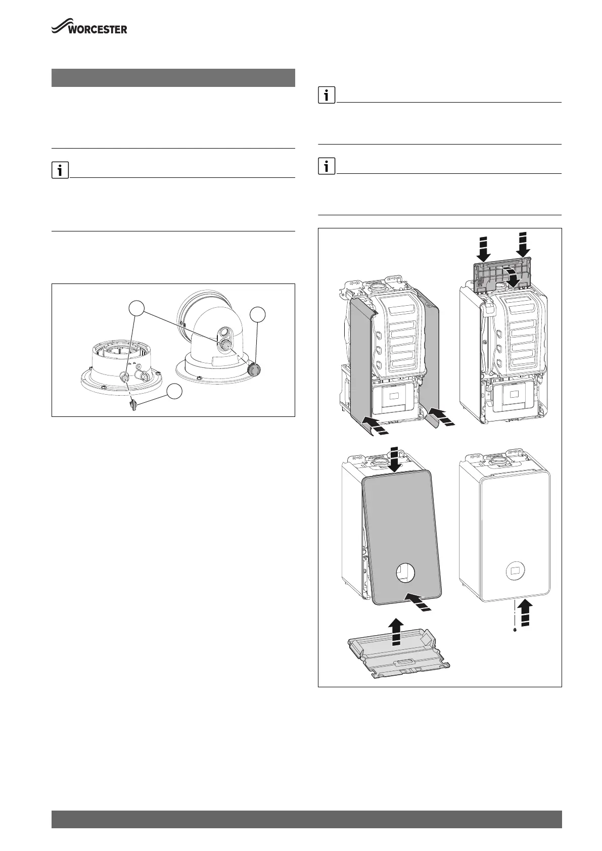
6.12 Finishing commissioning
6.12.1 Fitting the appliance casing
The front casing is to be secured at the bottom with one screw (as
supplied) against unauthorised removal (electrical safety).
▶ Always secure the casing with this screw.
▶ Remove the protective films from the boiler display before handing
over to the user.
Fig. 67 Fitting the appliance casing
[1] side covers
[2] top
[3] front
[4] bottom
0010015569-001
1
3
2
0010023240-002
3b.
1.
3a. 4.
2.

 Loading...