June 2014
2-5
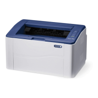
Xerox® Phaser® 3020 Printer Service Manual
08-100 , 08-500
Status Indicator RAPs
08-100 Paper Feed Fault
The lead edge was not detected by the Paper Feed Sensor.
BSD-Reference: 1.1 AC Low Voltage and High Voltage Power / Interlocks
BSD-Reference: 7.1 Paper Feed and Registration
Initial Actions
NOTE: When clearing any jams, see if the Lead Edge of the Jammed Sheet reached the
Retard Roller.
Clear any jammed sheets. Refer to Section 7: Troubleshooting, in the Xerox® Phaser® 3020
User Guide for detailed instructions on clearing paper jams.
Procedure
Check the Actuator on the Feed Sensor. The Actuator moves freely.
YN
Replace the Feed Sensor Actuator (REP 1.12), PL 3.3.
Check the position of the jammed sheet The Lead Edge reached the Retard Roller
YN
Enter Diagnostic (EDC) Mode. Select: [DC330 Component Control, 101-Clutch, Tray 1
Pick up] to engage the drive to pick up paper from tray 1 The clutch engages.
YN
• Check the Feed Clutch connections on the Main PWBs for contamination.
Clean as necessary.
• Check that the circuits from the Feed Clutch to the LVPS / HVPS for an open to
short circuit.
• If the circuits are good, replace the Feed Clutch (REP 1.16), PL 3.3.
In Diagnostics Mode. Select: [102-Sensor, Feed Sensor] to block and clear the Paper
Feed Sensor. The signal changes.
YN
• Check that the connection is secure and no contamination or damage is
present.
• Check that there is no damage or contamination on any connectors from the
Feed Sensor to the LVPS / HVPS PWB. Repair as necessary.
• Replace the Paper Feed Sensor (REP 1.2), PL 3.3.
Perform SCP Final Actions.
If the problem is intermittent, recheck the cables and look for a cable that is binding.
08-500 Paper Jam in Exit Area Fault
The machine has detected a paper jam in the Exit Area.
BSD-Reference: 7.1 Paper Feed and Registration
Initial Actions
• Open the Top Cover and remove jammed sheets from exit area. Refer to Section 7: Trou-
bleshooting, in the Xerox® Phaser® 3020 User Guide for detailed instructions on clearing
paper jams.
• Check the Paper Guides for proper position.
• Power Off the machine, then power On while holding the WPS button to reboot the
machine.
Procedure
Enter Diagnostic (EDC) Mode. Select: [DC330 Component Control, 102-Sensor, Exit Sens]
to block and clear the Exit Sensor. The Exit Sensor is OK.
YN
• Check for an open or short circuit and that no contamination is present.
• Replace the Exit Sensor PL 3.3.
In Diagnostics, go to [102-Sensor, Registration] to activate and deactivate the Registration
Sensor. The signal changes.
YN
• Check for an open or short circuit and that no contamination is present.
• Replace the Feed Sensor PWB (REP 1.2), PL 3.3.
Inspect the Exit Roller and Drives for wear or damage. Replace if needed.
 Loading...
