AC701 Evaluation Board www.xilinx.com 55
UG952 (v1.3) April 7, 2015
Feature Descriptions
Switches
[Figure 1-2, callout 26–27]
The AC701 board includes a power and a configuration switch:
• Power on/off slide switch SW15 (callout 26)
• FPGA_PROGRAM_B SW14, active-Low (callout 27)
Power On/Off Slide Switch SW15
[Figure 1-2, callout 26]
The AC701 board power switch is SW15. Sliding the switch actuator from the Off to On
position applies 12V power from J49, a 6-pin mini-fit connector. Green LED DS22
illuminates when the AC701 board power is on. See
Power Management for details on the
onboard power system.
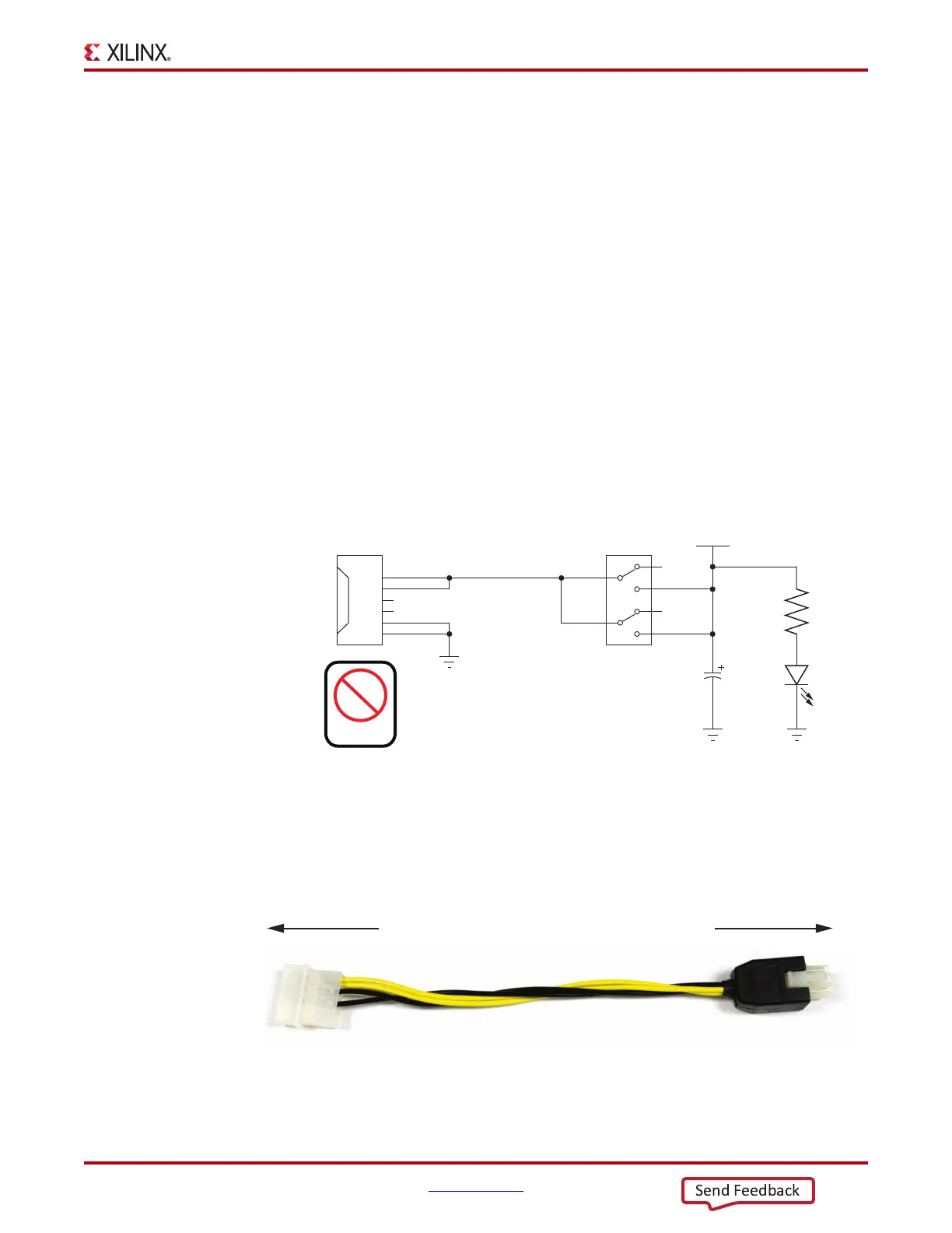
Caution! Do NOT plug a PC ATX power supply 6-pin connector into J49 on the AC701 board
The ATX 6-pin connector has a different pinout than J49. Connecting an ATX 6-pin connector into
J49 damages the AC701 board and voids the board warranty.
Figure 1-38 shows the simplified diagram of the power connector J49, power switch SW15
and indicator LED DS22.
The AC701 Evaluation Kit provides the adapter cable shown in Figure 1-39 for powering
the AC701 board from the ATX power supply 4-pin peripheral connector. The Xilinx part
number for this cable is 2600304, and is equivalent to Sourcegate Technologies part number
AZCBL-WH-1109-RA4. For information on ordering this cable, see
[Ref 24].
X-Ref Target - Figure 1-38
Figure 1-38: Power On/Off Switch SW15
X-Ref Target - Figure 1-39
Figure 1-39: ATX Power Supply Adapter Cable
UG952_c1_33_101612
VCC12 P IN
VCC12 P
R369
1kΩ
1%
GND
1
2
3
4
SW15
C539
330μF
25V
GND
DS22
5
6
J49
1
2
3
4
5
6
12V
N/C
COM
12V
N/C
COM
GND
Power
PCIe
UG952_c1_34_101612
To ATX 4-Pin Peripheral
Power Connector
To J49 on AC701 Board