MicroBlaze Development Kit Spartan-3E 1600 Edition User Guide 115
UG257 (v1.1) December 5, 2007 www.xilinx.com
R
Chapter 15
Expansion Connectors
The MicroBlaze Development Kit board provides a variety of expansion connectors for
easy interface flexibility to other off-board components. The board includes the following
I/O expansion headers (see Figure 15-1):
x A Hirose 100-pin edge connector with 43 associated FPGA user-I/O pins, including
up to 15 differential LVDS I/O pairs and two Input-only pairs
x Three 6-pin Peripheral Module connections
x Landing pads for an Agilent or Tektronix connectorless probe
Hirose 100-pin FX2 Edge Connector (J3)
A 100-pin edge connector is located along the right edge of the board (see Figure 15-1). This
connector is a Hirose FX2-100P-1.27DS header with 1.27 mm pitch. Throughout the
documentation, this connector is called the FX2 connector.
As shown in Figure 15-2, 43 FPGA I/O pins interface to the FX2 connector. All but five of
these pins are true, bidirectional I/O pins capable of driving or receiving signals. Five pins,
FX2_IP<38:35> and FX2_IP<40> are Input-only pins on the FPGA. These pins are
highlighted in light green in Table 15-1 and cannot drive the FX2 connector but can receive
signals.
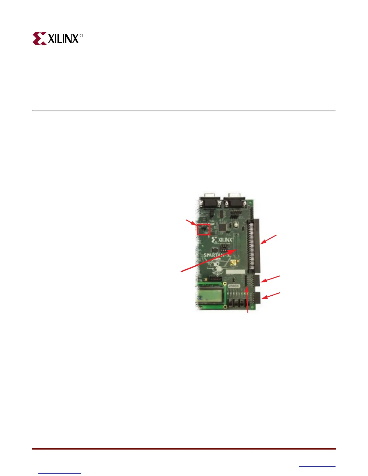
Figure 15-1: Expansion Headers
43 I/O connections, high-performance
J4 6-pin Accessory Header
J1 6-pin Accessory Header
J2 6-pin Accessory Header
Hirose 100-pin FX2 Connector, J3
Default is 3.3V, set to 2.5V for differential I/O
Jumper JP9, I/O Bank 0 Voltage
J6 Probe Landing Pads
Connectorless logic analyzer probes
UG257_15_01_060806