14 MicroBlaze Development Kit Spartan-3E 1600 Edition User Guide
www.xilinx.com UG257 (v1.1) December 5, 2007
Chapter 2: Switches, Buttons, and Knob
R
Push-Button Switches
Locations and Labels
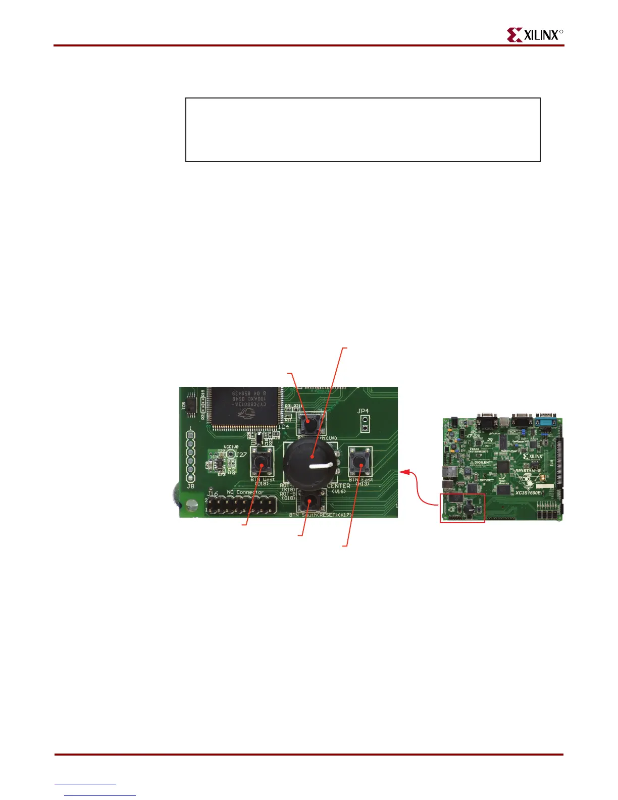
The MicroBlaze Development Kit board has four momentary-contact push-button
switches, shown in Figure 2-3. The push buttons are located in the lower left corner of the
board and are labeled BTN_NORTH, BTN_EAST, BTN_SOUTH, and BTN_WEST. The
FPGA pins that connect to the push buttons appear in parentheses in Figure 2-3 and the
associated UCF appears in Figure 2-5.
Operation
Pressing a push button connects the associated FPGA pin to 3.3V, as shown in Figure 2-4.
Use an internal pull-down resistor within the FPGA pin to generate a logic Low when the
button is not pressed. Figure 2-5 shows how to specify a pull-down resistor within the
UCF. There is no active debouncing circuitry on the push button.
Figure 2-2: UCF Constraints for Slide Switches
NET "SW<0>" LOC = "L13" | IOSTANDARD = LVTTL | PULLUP ;
NET "SW<1>" LOC = "L14" | IOSTANDARD = LVTTL | PULLUP ;
NET "SW<2>" LOC = "H18" | IOSTANDARD = LVTTL | PULLUP ;
NET "SW<3>" LOC = "N17" | IOSTANDARD = LVTTL | PULLUP ;
UG257_02_060206
Figure 2-3: Four Push-Button Switches Surround Rotary Push-Button Switch
UG257_02_03_061306
Spartan-3E
Development Board
Rotary Push Button Switch
ROT_A:(K18) requires an internal pull-up
ROT_B:(G18) requires an internal pull-up
ROT_Center:(V16) requires an internal pull-down
BTN_NORTH (V4)
BTN_WEST (D18)
BTN_SOUTH (K17)
BTN_EAST (H13)
Notes:
1. All BTN_* push-button inputs require an internal pull-down resistor.
2. BTN_SOUTH is also used as a soft reset in some FPGA applications